
CONFIGURATION TOOLKIT User guide
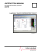


53HC2600 INSTRUCTION MANUAL
Contents iii
7.0 - TROUBLESHOOTING ........................................................55
7.1 SERIAL.386 File Installation Instructions ....................................................55
7.2 Documenter Problems.................................................................................56
7.3 Display Problems.........................................................................................56
7.3.1 THREED.VBX Display Problems ...................................................57
7.4 COM Port Selection.....................................................................................57
8.0 - MICRO-MITE CONTROLLER OPTIONS............................59
8.1 Connecting the Option Modules ..................................................................59
8.2 Communications Module .............................................................................59
8.3 2DI/2DO Option Module ..............................................................................59
8.4 Universal Ananlog Input Module..................................................................60
Appendix A - GLOSSARY OF TERMS ...................................... 61
Appendix B - DATABASE CROSS REFERENCE ..................... 63
Appendix C - MENUS AND TOOLBAR BUTTONS ................... 75
LIST OF FIGURES
Figure 2-1. Run Dialog Box ................................................................................5
Figure 2-2. System Properties Window, General Tab Displayed ........................7
Figure 2-3. Hardware Key for Use with LoopMaster System Software ..............8
Figure 2-4. Menus for Uninstalling LoopMaster Software, Method 1 ................14
Figure 2-5. Uninstalling LoopMaster Software, Method 2 .................................15
Figure 3-1. The Online or Offline? Dialog Box ..................................................17
Figure 3-2. Creating a New Offline Configuration .............................................18
Figure 3-3. Main LoopMaster Window - Example ............................................19
Figure 3-4. Standard AI Dialog Box ..................................................................20
Figure 3-5. Adding Information for the Documenter Report .............................21
Figure 3-6. Documenter Report, Sample First Page ........................................22
Figure 3-7. Documenter Report, Last Page, Rear Connections Example ........23
Figure 3-8. Selecting the C Scheme A Input Button .........................................25
Figure 3-9. Connection Drawing Example, FNC Output X Source ...................25
Figure 3-10. Connection Drawing Example, AI1 Source ..................................26
Figure 3-11. Equation Constant Configuration Example ...................................27
Figure 3-12. Sample Control Scheme Window ................................................28
Figure 3-13. SAMPLE.cn1.Output1 Dialog Window .........................................28
Figure 4-1. RS-232 Single Controller Cabling ..................................................32
Figure 4-2. Datalink Cabling .............................................................................33
Figure 4-3. RS-232/485 Cable ..........................................................................34
Figure 4-4. ITB Track Clearances .....................................................................35