Micro-DCI 4-Channel Indicator Totalizer 53IT5100B Instruction Manual
53IT5100B Indicator/Totalizer INSTRUCTION MANUAL MicroMod Automation & Controls, Inc. The Company MicroMod Automation & Controls is dedicated to improving customer efficiency by providing the most cost-effective, application-specific process solutions available. We are a highly responsive, application-focused company with years of expertise in control systems design and implementation. We are committed to teamwork, high quality manufacturing, advanced technology and unrivaled service and support.
53IT5100B Indicator/Totalizer INSTRUCTION MANUAL 1 INTRODUCTION ......................................................................................................................................... 1 1.1 1.2 2 PRODUCT OVERVIEW .............................................................................................................................. 1 SPECIFICATIONS .....................................................................................................................................
53IT5100B Indicator/Totalizer INSTRUCTION MANUAL IMPORTANT NOTICE All software, including design, appearances, algorithms and source code is copyrighted by MicroMod Automation & Controls, Inc. and is owned by MicroMod or its suppliers.
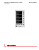
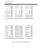
3IT5100B Indicator/Totalizer INSTRUCTION MANUAL 1 INTRODUCTION 1.1 Product Overview The 53IT5100B provides a suite of six operator displays to monitor process activity for up to four independent process variables and also provides integration and totalization for each of the four process variables. The displays are of three types: dynamic bar graph, digital readout, and alarm summary. There are three bar graph displays, two digital readout displays, and one alarm summary display.
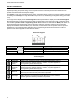
53IT5100B Indicator/Totalizer INSTRUCTION MANUAL input/output wiring and power wiring; and a compact instrument case that protects the instrument main printed circuit board and internal power supply. The display is a 96 X 48 gas discharge dot matrix, contrasted orange-on-black to enhance visibility and ease of reading. The intensity is a range selectable entry from 0 to 7, with 0 being the brightest setting (see Table 4-10).
53IT5100B Indicator/Totalizer INSTRUCTION MANUAL Quad Bar Graph (Chs. 1-4) Dual Bar Graph (Chs. 1&2) Quad Process Digital Readout Quad Totalizer Digital Readout Dual Bar Graph (Chs. 3&4) Alarm Summary Figure 1-1.
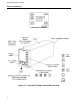
53IT5100B Indicator/Totalizer INSTRUCTION MANUAL INPUT/OUTPUT DIAGRAM Figure 1-2.
53IT5100B Indicator/Totalizer INSTRUCTION MANUAL Setup of the 53IT5100B can be done using the buttons on the horizontal and vertical keypads. It can also be done via the MicroTools configuration software package, Directly beneath the horizontal keypad and concealed behind the front panel pull-down door is the RS-232 Configuration Port which accept the configuration cable that provides interface between the instrument and MicroTools running on a personal computer.
53IT5100B Indicator/Totalizer INSTRUCTION MANUAL 1.
53IT5100B Indicator/Totalizer INSTRUCTION MANUAL 1.3 Specifications Item Power Range (as specified in model number) Power Consumption (ac/dc operation) Internal Power Supply: Available Power Output for Transmitters Output Ripple Specification(s) 22 - 26 V dc 108 - 132 V rms 216 - 264 V rms 50/60 Hz 36 VA maximum 25 V dc ± 1 V dc @ 80 mA maximum, short circuit protected.
53IT5100B Indicator/Totalizer INSTRUCTION MANUAL Item Environmental Characteristics Controlled Environment Enclosed temperature controlled location (Class A and B per ISA-S71.01 1985) Ambient Temperature Limits 4 -52°C (40 - 125°F) Relative Humidity Limits 10 - 90% maximum Temperature Effects on Accuracy ± 0.28% per 28°C (50°F) change from reference temperature 25°C (77°F) Transient Immunity (all circuits) ANSI C37.90a - 1974/IEEE Std 472-974: Ring Wave: 1.5 MHz, 3 kV, 60 pulses/s for 2.
53IT5100B Indicator/Totalizer INSTRUCTION MANUAL 2 INSTALLATION 2.1 Inspection A list of all items in the shipment is attached to the shipping container. Inspect the equipment upon arrival for damage that may have occurred during shipment. All damage claims should be reported to the responsible shipping agent before installation is attempted. If damage is such that faulty operation is likely to result, the MicroMod Customer Service Department should be notified.
53IT5100B Indicator/Totalizer INSTRUCTION MANUAL 2.3.2 Mounting Procedure For single and multiple case mounting the instruments are furnished with a trim collar (mounting frame). Figure 2-2 illustrates the installation and use of the trim collar (mounting frame). Trim collars (mounting frames) are available in various sizes and are supplied to conform with the particular panel cut-out. NOTE: Mounting brackets and trim collars (mounting frames) are packaged separately.
53IT5100B Indicator/Totalizer INSTRUCTION MANUAL NOTES: 1. DIMENSIONS ARE IN INCHES. DIMENSIONS IN BRACKETS ( ) ARE IN MILLIMIETERS. 2. DIMENSIONS GUARANTEED ON CERTIFIED PRINTS ONLY. 3. CASE MOUNTING HARDWARE SUPPLIED UNLESS OTHERWISE SPECIFIED. 4. THIS DRAWING IS THIRD-ANGLE PROJECTION AS SHOWN 5. UNLESS OTHERWISE INDICATED ALL TOLERANCES ARE ± 1/16 (1.6) Figure 2.
53IT5100B Indicator/Totalizer INSTRUCTION MANUAL Figure 2-2. Single or Multiple Panel Mounting Figure 2-3.
53IT5100B Indicator/Totalizer INSTRUCTION MANUAL 2.4 Power & Signal Wiring PREPARATORY: The 53IT5100B can be configured for one to four analog inputs (ANI0-3), one analog output (ANO0), two control contact inputs (CCI0 and 1), two control contact outputs (CCO0 and 1) and Datalink network interconnectivity. Therefore, prior to making electrical connections, the particular instrument configuration should be determined with all assigned inputs and outputs identified to assure proper signal routing.
53IT5100B Indicator/Totalizer INSTRUCTION MANUAL Figure 2-4.
53IT5100B Indicator/Totalizer INSTRUCTION MANUAL Figure 2-54.
53IT5100B Indicator/Totalizer INSTRUCTION MANUAL 2.4.1 Power Wiring Refer to the instrument model number to verify the power input requirements: 53IT511nB21AAA – AC Power 53IT512nB21AAA – DC Power 2.4.1.1 DC Power Reference Figure 2-4 and connect the remote 24 V dc power supply to the instrument as follows: 1. Connect (+) input line, via remote SPST switch, to terminal L1. 2. Connect (-) input line to the system bus bar.
53IT5100B Indicator/Totalizer INSTRUCTION MANUAL 2.4.3 Datalink Communication Datalink is an interrogator/responder serial interface capable of supporting 32 instruments on a single network. It uses an RS485 physical interface. The Datalink wiring diagram for this instrument is provided as Figure 2-5. Complete coverage of the Datalink is provided in the SUPERVISOR-PC Instruction Bulletin 53SU5000. 2.
53IT5100B Indicator/Totalizer INSTRUCTION MANUAL 18
53IT5100B Indicator/Totalizer INSTRUCTION MANUAL 3 DISPLAYS AND PUSH BUTTONS This section provides illustrations with item call-outs of the six operator displays, alarm overlays, and engineering mode overlays. Where applicable, datapoints are identified parenthetically with the display item call-outs. The datapoints are defined in Section 4.
53IT5100B Indicator/Totalizer INSTRUCTION MANUAL Figure 3-2. Dual Bar Graph (Channels 1 & 2) Figure 3-3.
53IT5100B Indicator/Totalizer INSTRUCTION MANUAL Figure 3-4. Quad Process Digital Readout Figure 3-5.
53IT5100B Indicator/Totalizer INSTRUCTION MANUAL Figure 3-6. Alarm Summary 3.2 Alarm Overlay Any one of the six operator displays can have the upper quadrant of the display overlaid with an ALARM indicator. An alarm indication warns of variation changes that exceed tolerance limits; the process may require immediate attention. In the five illustrations of Figure 3-7, the process variable exceeded Alarm Limit 1 for ANI1.
53IT5100B Indicator/Totalizer INSTRUCTION MANUAL Figure 3-7.
53IT5100B Indicator/Totalizer INSTRUCTION MANUAL 3.2.1 Front Panel Pushbuttons The front panel push buttons are repeated here from Section 1 because they are used in the engineering mode display overlay examples to enter a key password, display a datapoint, and alter a datapoint. To the right of the display is the vertical keypad and directly beneath the display is the horizontal keypad.
53IT5100B Indicator/Totalizer INSTRUCTION MANUAL 3.3 Engineering Mode Overlays The engineering mode overlays are used to make the necessary parameter entry selections for the operator displays and to configure the Datalink communications port. The entries are made to addressed datapoints via the overlay single edit line at the bottom of the display. It should be noted that engineering mode has a 20 second timeout if it is accessed and its functions (e.g., configure or display) are not used. 3.3.
53IT5100B Indicator/Totalizer INSTRUCTION MANUAL Figure 3-8.
53IT5100B Indicator/Totalizer INSTRUCTION MANUAL 3.3.2 Displaying a Datapoint The following procedure illustrates how to display the contents of datapoint C175, which is ANI2 Alarm Limit 1. Figure 3-9 contains supporting illustrations for the display procedure described in Table 3-2. (Notice in these illustrations that ANI-2 Alarm Limit 1 is set at 80.) Table 3-2. Procedure to Display a Datapoint Step 1 Press Once Shift Result Press to Locate Result Puts instrument in engineering mode.
53IT5100B Indicator/Totalizer INSTRUCTION MANUAL 3.3.3 Altering a Datapoint The procedure in Table 3-3 illustrates how to alter the contents of datapoint C175, which is ANI2 Alarm Limit 1, from 80 to 90. Figure 3-10 is provided to show the maximum input character length for the engineering mode edit line. The edit line can accept ten characters. The full ten character field is used primarily for the A type datapoint text strings (tag names).
53IT5100B Indicator/Totalizer INSTRUCTION MANUAL 4 CONFIGURATION PARAMETERS The configuration parameters provide the latitude to define the instrument’s personality attributes, so that while still functioning within its designed specifications, it can perform application requirements with greater refinement. Typical configuration parameters are the instrument’s indicator zero point and span, the display tag names, engineering units of the displayed process value, and alarm limits, etc.
53IT5100B Indicator/Totalizer INSTRUCTION MANUAL Table 4-2. Database Modules Item 1 2 Purpose Analog Input Module This module is used to configure the voltage input characteristics (e.g., input voltage range) and how the input signal is interpreted (linear or square root representation). The primary purpose of this module is to set the 0 - 20 mA output signal relative to the displayed percent output.
53IT5100B Indicator/Totalizer INSTRUCTION MANUAL Table 4-3. Analog Input (ANI) Module Purpose: This module is used to configure input voltage characteristics (e.g., input voltage range), and how the input signals are interpreted (linear or square root representation).
53IT5100B Indicator/Totalizer INSTRUCTION MANUAL Figure 4-1. ANI0-3 Figure 4-2. ANO0 NOTE: These figures are graphical representations of the signal conditioning that occurs on the instrument main board. They are provided for reference purposes only.
53IT5100B Indicator/Totalizer INSTRUCTION MANUAL Table 4-4. Analog Output (ANO) Module Purpose: The primary purpose of this module is to set the 0 - 20 mA output signal relative to the displayed percent and to select the analog input signal (ANI0-3) that is to be routed to the analog output (ANO0). Title Symbol ANO0 Default Attribute Datapoint Analog Output ANO0 C000 0 The value in this datapoint represents the (Display Only) percent of output to be generated by hardware (e.g., 100% output = 20 mA).
53IT5100B Indicator/Totalizer INSTRUCTION MANUAL Table 4-5. Contact Input Module (CCI) Purpose: This module allows the action of the CCIs to be reversed (normally a closed contact = 1, but can be changed to = 0). Datapoin Title Symbol CCI t Default Attribute Contact CCI0 CCI0 L000 0 When open, a 4 -24 V dc input signal = 0 when IINV = Input CCI1 CCI1 L001 0 0. (Display When open, a 4 -24 V dc input signal = 1 when IINV = Only) 1. When closed, a < 1 V dc input signal = 1 when IINV = 0.
53IT5100B Indicator/Totalizer INSTRUCTION MANUAL Table 4-6. Contact Output Module (CCO) Purpose: This module allows the action of the CCOs to be reversed (normally a closed contact = 1, but can be changed to = 0) and is used to select the signal or condition that activates the CCO.
53IT5100B Indicator/Totalizer INSTRUCTION MANUAL Table 4-7. Alarm Module Purpose: The primary purpose of this module is to set the instrument’s Alarm Index mode, Alarm Limits 1 & 2, and Alarm Dead Band. Title Symbol CCO Data-point Default Attribute This parameter defines the Alarm Active (PA1 & PA2) interpretation of the two Alarm Limits (PL1 & PL2).
53IT5100B Indicator/Totalizer INSTRUCTION MANUAL Table 4-7. Alarm Module (continued) Purpose: The primary purpose of this module is to set the instrument’s Alarm Index mode, Alarm Limits 1 & 2, and Alarm Dead Band.
53IT5100B Indicator/Totalizer INSTRUCTION MANUAL Table 4-8. Totalizer Module Purpose: The totalizers provide a running total of each analog input (ANI0-3). This module is used to set input scaling factors, rollover and dropout values, and to define display tags for each totalizer. Title Symbol TM Datapoint Default Attribute Tag Name TMTAG0 TMTAG1 TMTAG2 TMTAG3 TM0 TM1 TM2 TM3 A092 A094 A096 A098 TOTAL-0 TOTAL-1 TOTAL-2 TOTAL-3 Eng.
53IT5100B Indicator/Totalizer INSTRUCTION MANUAL Table 4-8. Totalizer Module (continued) Purpose: The totalizers provide a running total of each analog input (ANI0-3). This module is used to set input scaling factors, rollover and dropout values, and to define display tags for each totalizer.
53IT5100B Indicator/Totalizer INSTRUCTION MANUAL Table 4-9. Communication Module Purpose: This module is used to configure the Datalink port parameters (e.g., baud rate, parity selection, etc.). Title Symbol Datapoint Default Attribute Instrument Address IA B001 0 It identifies the address of this instrument on the Datalink network. Each unit connected to the Datalink network must have its own unique address. Valid addresses are from 0 -31.
53IT5100B Indicator/Totalizer INSTRUCTION MANUAL Table 4-10. System Module Purpose: This module is used to set the instrument tag name and the display brightness. System Title Symbol Module Default Attribute Datapoint Display Brightness Index B012 4 Model Number Low (Display Only) A190 Factory Set It contains the first ten characters of the model number. Model Number High (Display Only) A191 Factory Set It contains the last ten characters of the model number.
53IT5100B Indicator/Totalizer INSTRUCTION MANUAL 42
53IT5100B Indicator/Totalizer INSTRUCTION MANUAL 5 MAINTENANCE NOTE: The factory set calibration constants for ANI0-3 and ANO0 are applicable only for the main printed circuit board supplied in the particular instrument. This data is recorded on a calibration sheet supplied with the instrument. The data should be retained to facilitate easy field recalibration in the event one or more of the constants is inadvertently changed. 5.
53IT5100B Indicator/Totalizer INSTRUCTION MANUAL NOTE: When communicating with MicroMod for replacement of the main PCB, reference the unit’s serial number to ensure the correct replacement assembly is supplied. The necessary ordering information is provided on the instrument data tag and on the manufacturing specification sheet supplied with that particular controller. In the event of a hardware malfunction, a replacement PCB can be quickly substituted for the defective assembly to minimize downtime.
53IT5100B Indicator/Totalizer INSTRUCTION MANUAL 5.6 Parts List The parts list is provided in Table 5-1 and the parts breakdown is illustrated in Figure 5-1. Note that these boards are for the 53IT5000B, not the 53IT5000A. Contact MicroMod for more information on spare parts availability for the 53IT5000 Design Level A. Table 5-1.
53IT5100B Indicator/Totalizer INSTRUCTION MANUAL Figure 5-1.
53IT5100B Indicator/Totalizer INSTRUCTION MANUAL Figure 5-3.
53IT5100B Indicator/Totalizer INSTRUCTION MANUAL 48
IT5100B Indicator/Totalizer INSTRUCTION MANUAL Appendix A: Discrete Contact Output CCO’s The discrete output CCOs are not mechanical contact closures but NPN Transistors that are analogous to single pole, single throw switches with one terminal connected to power common. This circuit type layout is commonly called an Open Collector Output. (See Figure A-1.) Capability limits of each CCO are as follows: 50 mA maximum current flow when closed. 30 V dc maximum tolerance voltage when open.
53IT5100B Indicator/Totalizer INSTRUCTION MANUAL Figure A-1. CCO Circuit and its Equivalent Figure A-2.
53IT5100B Indicator/Totalizer INSTRUCTION MANUAL Figure A-3. Operating CCOs in Parallel Figure A-4. CCO with Solid State Relay Figure A-5.
53IT5100B Indicator/Totalizer INSTRUCTION MANUAL 52
53IT5100B Indicator/Totalizer INSTRUCTION MANUAL Appendix B : Communications Two digital communication channels are provided with this instrument: RS-232 serial configuration port, accessed via a 5 pin mini-DIN connector located under the pulldown door on the front panel (see Figure 1-2). It is used to configure instrument parameters for selected operational characteristics. The parameters are configured with Micro-Tools software running on a customer supplied PC.
53IT5100B Indicator/Totalizer INSTRUCTION MANUAL Table B-1. Communication Module Purpose: This module is used to configure the Datalink port parameters (e.g., baud rate, parity selection, etc.). Title Datapoint Setup Default Attribute Instrument Address B01 S 0 Baud Rate B02 S 253 No Parity L256 0 0 No Byte Stuffing L258 0 0 Datalink Disable L257 0 0 It identifies the address of this instrument on the Datalink network.
53IT5100B Indicator/Totalizer INSTRUCTION MANUAL Protocol The Datalink protocol requires the host to initiate all transactions. There are two basic categories for all of the Datalink message types: Interrogate - used to read data from an addressed instrument, and Change used to alter a value in an addressed instrument. The addressed instrument decodes the message and provides an appropriate response. The protocol definitions for the Datalink message types are provided in Table B-2. Table B-2.
53IT5100B Indicator/Totalizer INSTRUCTION MANUAL 4. ACKNOWLEDGE - This message signals the addressed instrument that its last echoed change message was received correctly; the instrument performs the change requested. 01111110 80H + I.A. INSTRUMENT TO HOST: 1. RESPONSE - This message furnishes the data requested by the INTERROGATE command of the Host. It is also used to echo back the previous CHANGE message of the Host. 01111110 20H + I.A.
53IT5100B Indicator/Totalizer INSTRUCTION MANUAL + I.A. 4. Instrument performs the change requested at end of the current program scan.
53IT5100B Indicator/Totalizer INSTRUCTION MANUAL Calculating Data Addresses If communications software must be generated to accommodate unique Datalink applications requirements, then the instrument memory address scheme must be known for proper data bit (e.g., L data type) and data byte (e.g., B, C, H, and A data types) memory location determination. NOTE: Numbers used in this section that are expressed in hexadecimal notation (base 16) are identified with an H after the number.
53IT5100B Indicator/Totalizer INSTRUCTION MANUAL Table B-3. Instrument Memory Address Scheme (continued) Data Type H A (F)* Base Memory Address F00H 1400H Byte Size 5 10 (A) 5 (F)* Data Format Represents high precision floating point values that have a resolution of one part in 2 billion (31 bits) and a dynamic range of ± 1038 . The first four bytes represent a 2’s complement notation in fractional form (2-n) whose absolute value is between 0.5 and 0.9999.
53IT5100B Indicator/Totalizer INSTRUCTION MANUAL Appendix C: Database The database contains five datapoint types. Each datapoint type represents a specific data format: whole integers, alphanumeric text strings, etc. The datapoint types are defined in Table C-1 and the database is listed in alphanumeric order in Table C-2. The gray-tone shading in the Symbol cell of a datapoint indicates the datapoint does not have an assigned symbol. Table C-1.
53IT5100B Indicator/Totalizer INSTRUCTION MANUAL Table C-2.
53IT5100B Indicator/Totalizer INSTRUCTION MANUAL Table C-2.
53IT5100B Indicator/Totalizer INSTRUCTION MANUAL Table C-2.
53IT5100B Indicator/Totalizer INSTRUCTION MANUAL Table C-2.
53IT5100B Indicator/Totalizer INSTRUCTION MANUAL 65
53IT5100B Indicator/Totalizer INSTRUCTION MANUAL 66
The Company’s policy is one of continuous product improvement and the right is reserved to modify the information contained herein without notice, or to make engineering refinements that may not be reflected in this bulletin. MicroMod Automation & Controls, Inc. assumes no responsibility for errors that may appear in this manual. © 2004 MicroMod Automation & Controls, Inc. Printed in USA PN24479 Issue 1, 8/2013 MicroMod Automation & Controls, Inc. 75 Town Centre Drive Rochester, NY USA 14623 Tel.