
Owner's manual

53IT5100B Indicator/Totalizer
INSTRUCTION MANUAL
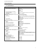
1.3 Specifications
Item Specification(s)
Power
Range (as specified in model number) 22 - 26 V dc
108 - 132 V rms
216 - 264 V rms
50/60 Hz
Power Consumption (ac/dc operation) 36 VA maximum
Internal Power Supply:
Available Power Output for Transmitters
25 V dc ± 1 V dc @ 80 mA maximum, short circuit protected.
Output Ripple 200 mV p-p maximum
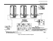
Analog Input (ANI0-3) Signals (all analog in-puts are referenced to signal common)
Quantity 4 (ANI0, ANI1, ANI2, and ANI3)
Signal Range 0 -5 V dc or 1 -5 V dc (0 -20 mA and 4 -20 mA dc respectively).
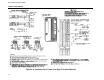
NOTE: The rear terminal board has the appropriate resistors
for ANI0 and ANI1.
Input Impedance 1 megohm minimum for voltage inputs; value of ranging resistor
for current signals.
Measurement Accuracy ± 0.1% of span
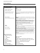
Contact Input CCI0/1 Signals (are referenced to power common)
Quantity 2 (CCI0 and CCI1)
Type discrete input
Permitted Contact Resistance 100 ohm maximum
Open/Close Contact Duration for open recognition: 0.05 seconds minimum
for closed recognition: 0.05 seconds minimum
Contact Recognition Level Closed
1 V dc maximum
Contact Recognition Level Open 4 V dc to 24 V dc
Analog Output (ANO0) Signal (is referenced to power common)
Quantity 1 (ANO0)
Signal Range 0 -20 mA dc (4 -20 mA dc typically)
Load Range 0 - 750 ohms
Accuracy ± 0.2% of span
Switch Output (CCO0, CCO1) Signals (are referenced to power common)
Quantity 2 (CCO0 and CCO1)
Type
solid state switch output
Configuration solid state equivalent of a single pole single throw, normally
open or normally closed contacts referenced to common.
Voltage 30 V dc maximum
Current 50 mA dc maximum
Datalink Communication
RS485, four wire, asynchronous; baud rates 300 to 28,800
Sampling and Update Attributes
Program Scan Rate 0.05 seconds
Analog Input Signal Sampling Rate 0.05 seconds
Contact Input Signal Sampling Rate 0.05 seconds
Display Update 0.10 seconds
Output Signal Update 0.05 seconds
7