
Owner's manual

53IT5100B Indicator/Totalizer
INSTRUCTION MANUAL
2.4.1 Power Wiring
Refer to the instrument model number to verify the power input requirements:
53IT511nB21AAA – AC Power
53IT512nB21AAA – DC Power
2.4.1.1 DC Power
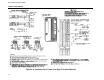
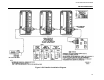
Reference Figure 2-4 and connect the remote 24 V dc power supply to the instrument as follows:
1.
Connect (+) input line, via remote SPST switch, to terminal L1.
2. Connect (-) input line to the system bus bar. The bus bar should be connected to a good earth
ground (#8 AWG wire is recommended). Individual wires should be run from the controller Power
Common (PC ) and Signal Common (SC ) terminals to the bus bar. The chassis should be grounded
by connecting terminal G to earth ground.
NOTE: Use of a common bus bar is recommended to minimize potential voltage differences that may
occur as the result of ground current loops, e.g., potential difference between separate signal grounds,
power grounds, etc.
2.4.1.2 AC Power
Reference Figure 2-4 and connect the specified line service (110-120, 220-240 V ac, 50 or 60 Hz) to the
ins
trument as follows:
1. Connect the phase or hot line L, via a remote power disconnect switch or circuit breaker, to terminal
L1.
2. Connect the neutral line N to terminal L2 for 110-120 V ac. Connect the neutral line N to terminal L3
for 220-240 V ac.
3. Connect Power Common to a good earth ground (#12 AWG wire is recommended). The instrument
case should be grounded by connecting terminal G to earth ground at the source of supply
(green/green-yellow ground).
All supply connections include surge protection rated at 275 V ac normal mode.
NOTE: To minimize possible interference, ac power wiring should be routed away from signal wiring.
2.4.2 Field Signal Wiring
2.4.2.1 Current/Voltage Input to AIN1 through AIN3
When the input signal is from a 4-20 mA current transmitter, a precision 250 ohms (+/-0.1%) resistor is
required. (The resistor tolerance is critical, as the resistor is used to accurately convert the current signal from
the transmitter, which is typically 4-20 mA, to a specified analog input voltage of 1 to 5 V dc). The back of the
rear terminal board has the appropriate resistors (R1 and R2, respectively) for ANI0 and ANI1. Resistor for
ANI2 and ANI3 are not supplied and must be installed as shown in the upper left corner of Figure 2-4. If the
input signal is already a voltage signal, its corresponding resistor should be removed.
2.4.2.2 Contact Input to CCI0 and CCI1
Separate contact input signals to CCI0 and CCI1 can be used for alarm inputs. One side of each
remote contact must be connected to power common as illustrated in Figure 2-4. Minimum opened
or closed recognition time for a remote contact must be 0.05 seconds.
2.4.2.3 Current Output from ANO0
A current output signal is available for re-transmission of one of the input signals ANI0 through
ANI3. Observe the proper polarity when connecting the output to another instrument.
2.4.2.4 Contact Outputs CCO0 and CCO1
Discrete contact outputs CCO0 and CCO1 are identified in Figure 2-4. Each discrete output is a
solid state switch with a rating of 30 V dc, 50 mA maximum. A CCO is referenced to power common.
When this contact is connected to an inductive load, an external arc suppression network is required
for contact protection.
16