
Owner's manual

53IT5100B Indicator/Totalizer
INSTRUCTION MANUAL
33
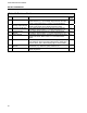
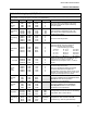
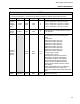
Table 4-4. Analog Output (ANO) Module
Purpose: The primary purpose of this module is to set the 0 - 20 mA output signal relative to the
displayed percent and to select the analog input signal (ANI0-3) that is to be routed to the analog
output (ANO0).
Title Symbol ANO0
Datapoint
Default Attribute
Analog Output
(Display Only)
ANO0 C000 0 The value in this datapoint represents the
percent of output to be generated by hardware
(e.g., 100% output = 20 mA).
Analog Output
Source
B100 0 This parameter determines which analog input
(ANI0-3) is routed to the analog output (ANO0).
The routing index values are as follows: 0 =
ANI0 →ANO0, 1 = ANI1 →ANO0 2 = ANI2
→ANO0, 3 = ANI3 →ANO0
0 -20 mA
Output
OZBASE0 L472 0
When a 0, the percentage output generates a 4
-20 mA signal. When set to 1 , the percentage
output generates a 0 -20 mA signal.
Calibrate Zero COZ0 B267
Calibrate
Span
COS0 C300
These parameters are factory set and should
not need adjustment under normal operation.
See Section 5.3 for adjustment.
Tag Name AOTAG0 A244 ANO0 The assignable 10 character name for ANO0.
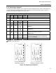
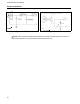
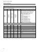
Figure 4-3. CCI0/1 Figure 4-4. CCO0/1
NOTE: These figures are graphical representations of the signal conditioning that occurs on the
instrument main board. They are provided for reference purposes only.