
Instruction Manual Owner's manual

5.7 DISCRETE OUTPUT MODULES (DO0-17)
The Discrete Output Modules (DO0-17) convert a logic level to a hardware contact condition. Outputs DO2-17 are active only when the
appropriate hardware options are installed. The 18 Discrete Output Modules are provided in Table 5-7. Each one can be configured
separately (total combined DIs and DOs for controller cannot exceed 18).
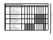
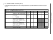
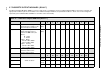
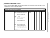
Table 5-7. Discrete Output Modules (DO0-17)
Title Definition Atom DO
0
DO
1
DO
2
DO
3
DO
4
DO
5
DO
6
DO
7
DO
8
Default
Discrete Output The value in this datapoint
represents the condition to be
generated by the hardware.
DO
(0-8)
L024 L025 L026 L027 L028 L029 L030 L031 L032 0
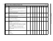
Output Invert This parameter specifies the
output signaling protocol
used for the
DO
value (see
above):
0
- 1-ON
1
- 0-ON
Output: Open,
INV 0, 1-ON DO=0
INV 1, 0-ON DO=1
Output: Closed,
INV 0, 1-ON DO=1
INV 1, 0-ON DO=0
INV
(0-8)
L288 L289 L290 L291 L292 L293 L294 L295 L296 0
Tag Name It is an assignable 10
character name for the
contact control output.
TAG A280 A281 A282 A283 A284 A285 A286 A287 A288
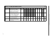
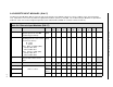
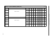
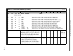
Title Definition Atom DO
9
DO
10
DO
11
DO
12
DO
13
DO
14
DO
15
DO
16
DO
17
Default
Discrete Output
Same as above.
DO
(9-17)
L033 L034 L035 L036 L037 L038 L039 L040 L041 0
Output Invert INV
(9-17)
L297 L298 L299 L300 L301 L302 L303 L304 L305 0
Tag Name TAG A289 A290 A291 A292 A293 A294 A295 A296 A297
5-10
53MC5000 Process Control Station