Micro-DCI Manual Loader 53ML5100 Instruction Manual
53ML5100B Manual Loader INSTRUCTION MANUAL MicroMod Automation & Controls, Inc. The Company MicroMod Automation & Controls is dedicated to improving customer efficiency by providing the most cost-effective, application-specific process solutions available. We are a highly responsive, application-focused company with years of expertise in control systems design and implementation. We are committed to teamwork, high quality manufacturing, advanced technology and unrivaled service and support.
53ML5100B Manual Loader INSTRUCTION MANUAL 1 INTRODUCTION ......................................................................................................................................... 1 1.1 1.2 2 PRODUCT OVERVIEW .............................................................................................................................. 1 SPECIFICATIONS .....................................................................................................................................
53ML5100B Manual Loader INSTRUCTION MANUAL IMPORTANT NOTICE All software, including design, appearances, algorithms and source code is copyrighted by MicroMod Automation & Controls, Inc. and is owned by MicroMod or its suppliers.
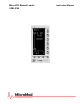
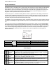
3ML5100B Manual Loader INSTRUCTION MANUAL 1 INTRODUCTION 1.1 Product Overview The 53ML5100B provides the capability to manually adjust and display one or two current outputs. Each output is independently configurable as a 0-20 mA or 4-20 mA signal. The Manual Loading Station can also accept two input process variables that are each presented on separate displays.
53ML5100B Manual Loader INSTRUCTION MANUAL vertical axis. Also, the vertical axis has a numeric range (zero and span). An input channel tag name appears in the upper left corner of the display. A digital readout for the analog output channel appears under the letters SP in the upper half of the display. The analog input measured units tag appears in the middle of the display and beneath it a digital readout appears under the letters PV.
53ML5100B Manual Loader INSTRUCTION MANUAL Figure 1-1.
53ML5100B Manual Loader INSTRUCTION MANUAL Figure 1-2.
53ML5100B Manual Loader INSTRUCTION MANUAL Setup of the 53ML5100 can be done using the buttons on the horizontal and vertical keypads. It can also be done via the MicroTools configuration software package. Directly beneath the horizontal keypad and concealed behind the front panel pull-down door is the RS-232 Configuration Port which accept the configuration cable that provides interface between the instrument and MicroTools running on a personal computer.
53ML5100B Manual Loader INSTRUCTION MANUAL 1.
53ML5100B Manual Loader INSTRUCTION MANUAL 1.3 Specifications Item Power Range (as specified in model number) Power Consumption (ac/dc operation) Internal Power Supply: Available Power Output for Transmitters Output Ripple Specification(s) 22 - 26 V dc 108 - 132 V rms 216 - 264 V rms 50/60 Hz 36 VA maximum 25 V dc ± 1 V dc @ 80 mA maximum, short circuit protected.
53ML5100B Manual Loader INSTRUCTION MANUAL Item Environmental Characteristics Controlled Environment Specification(s) Enclosed temperature controlled location (Class A and B per ISAS71.01 1985) Ambient Temperature Limits 4 -52°C (40 - 125°F) Relative Humidity Limits 10 - 90% maximum Temperature Effects on Accuracy ± 0.28% per 28°C (50°F) change from reference temperature 25°C (77°F) Transient Immunity (all circuits) ANSI C37.90a - 1974/IEEE Std 472-974: Ring Wave: 1.5 MHz, 3 kV, 60 pulses/s for 2.
53ML5100B Manual Loader INSTRUCTION MANUAL 2 INSTALLATION 2.1 Inspection A list of all items in the shipment is attached to the shipping container. Inspect the equipment upon arrival for damage that may have occurred during shipment. All damage claims should be reported to the responsible shipping agent before installation is attempted. If damage is such that faulty operation is likely to result, the MicroMod Customer Service Department should be notified.
53ML5100B Manual Loader INSTRUCTION MANUAL 2.3.2 Mounting Procedure For single and multiple case mounting the instruments are furnished with a trim collar (mounting frame). Figure 2-2 illustrates the installation and use of the trim collar (mounting frame). Trim collars (mounting frames) are available in various sizes and are supplied to conform with the particular panel cut-out. NOTE: Mounting brackets and trim collars (mounting frames) are packaged separately.
53ML5100B Manual Loader INSTRUCTION MANUAL NOTES: 1. DIMENSIONS ARE IN INCHES. DIMENSIONS IN BRACKETS ( ) ARE IN MILLIMIETERS. 2. DIMENSIONS GUARANTEED ON CERTIFIED PRINTS ONLY. 3. CASE MOUNTING HARDWARE SUPPLIED UNLESS OTHERWISE SPECIFIED. 4. THIS DRAWING IS THIRD-ANGLE PROJECTION AS SHOWN 5. UNLESS OTHERWISE INDICATED ALL TOLERANCES ARE ± 1/16 (1.6) Figure 2.
53ML5100B Manual Loader INSTRUCTION MANUAL Figure 2-2. Single or Multiple Panel Mounting Figure 2-3.
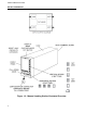
53ML5100B Manual Loader INSTRUCTION MANUAL 2.4 Power & Signal Wiring PREPARATORY: The 53ML5100 can be configured for one to four analog inputs (ANI0-3), one analog output (ANO0), two control contact inputs (CCI0 and 1), two control contact outputs (CCO0 and 1) and Datalink network interconnectivity. Therefore, prior to making electrical connections, the particular instrument configuration should be determined with all assigned inputs and outputs identified to assure proper signal routing.
53ML5100B Manual Loader INSTRUCTION MANUAL Figure 2-4.
53ML5100B Manual Loader INSTRUCTION MANUAL 15
53ML5100B Manual Loader INSTRUCTION MANUAL 2.4.1 Power Wiring Refer to the instrument model number to verify the power input requirements: 53ML511nB21AAA – AC Power 53ML512nB21AAA – DC Power 2.4.1.1 DC Power Reference Figure 2-4 and connect the remote 24 V dc power supply to the instrument as follows: 1. Connect (+) input line, via remote SPST switch, to terminal L1. 2. Connect (-) input line to the system bus bar. The bus bar should be connected to a good earth ground (#8 AWG wire is recommended).
53ML5100B Manual Loader INSTRUCTION MANUAL an instrumentation ground reference does not exist in the installation, an earth ground electrode should be established with an independent grounding rod or ground grid mesh.
53ML5100B Manual Loader INSTRUCTION MANUAL 18
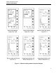
53ML5100B Manual Loader INSTRUCTION MANUAL 3 DISPLAYS AND PUSH BUTTONS This section provides illustrations with item call-outs of the six operator displays and engineering mode overlays. Where applicable, datapoints are identified parenthetically with the display item call-outs. The datapoints are defined in Section 4.
53ML5100B Manual Loader INSTRUCTION MANUAL Fig 3-2. Display 1 - Dual Channel Manual Loader (Chs. 1 & 2) Showing Channel 2 Selected Using the F3 Push Button Figure 3-3. Display 2 - Single Channel Manual Loader (Ch.
53ML5100B Manual Loader INSTRUCTION MANUAL Figure 3-4. Display 3 - Manual Loader with Analog Input (Ch. 1) Figure 3-5. Display 4 - Manual Loader with Analog Input (Ch.
53ML5100B Manual Loader INSTRUCTION MANUAL Figure 3-6. Display 5 - Analog Input Indicator with Setpoint Display (Ch. 1) Figure 3-6. Display 6 - Analog Input Indicator with Setpoint Display (Ch.
53ML5100B Manual Loader INSTRUCTION MANUAL 3.2 Front Panel Pushbuttons The front panel push buttons are repeated here from Section 1 because they are used in the engineering mode display overlay examples to enter a key password, display a datapoint, and alter a datapoint. To the right of the display is the vertical keypad and directly beneath the display is the horizontal keypad.
53ML5100B Manual Loader INSTRUCTION MANUAL 3.3 Engineering Mode Overlays The engineering mode overlays are used to make the necessary parameter entry selections for the operator displays and to configure the Datalink communications port. The entries are made to addressed datapoints via the overlay single edit line at the bottom of the display. It should be noted that engineering mode has a 20 second timeout if it is accessed and its functions (e.g., configure or display) are not used. 3.3.
53ML5100B Manual Loader INSTRUCTION MANUAL Figure 3-8.
53ML5100B Manual Loader INSTRUCTION MANUAL 3.3.2 Displaying a Datapoint The following procedure illustrates how to display the contents of datapoint C175, which is ANI2 Alarm Limit 1. Figure 3-9 contains supporting illustrations for the display procedure described in Table 3-2. Table 3-2. Procedure to Display a Datapoint Step 1 Press Once Shift Result Press to Locate Result Puts instrument in engineering mode. 2 3 Target Char. If DISPLAY does not appear, press F2.
53ML5100B Manual Loader INSTRUCTION MANUAL 3.3.3 Altering a Datapoint The procedure in Table 3-3 illustrates how to alter the contents of datapoint C175, which is ANI2 Alarm Limit 1, from 80 to 90. Figure 3-10 is provided to show the maximum input character length for the engineering mode edit line. The edit line can accept ten characters. The full ten character field is used primarily for the A type datapoint text strings (tag names).
53ML5100B Manual Loader INSTRUCTION MANUAL 28
53ML5100B Manual Loader INSTRUCTION MANUAL 4 CONFIGURATION PARAMETERS The configuration parameters provide the latitude to define the instrument’s personality attributes, so that while still functioning within its designed specifications, it can perform application requirements with greater refinement. Typical configuration parameters are the instrument’s indicator zero point and span, the display tag names, engineering units of the displayed process value, and alarm limits, etc.
53ML5100B Manual Loader INSTRUCTION MANUAL Table 4-2. Database Modules Item 1 2 30 Title Purpose Analog Input Module This module is used to configure the voltage/current input signals (e.g., 0-5 volts [0-20 mA], 1-5 volts [4-20 mA]) and how the two input signals are interpreted (linear or square root representation, with or without smoothing). It is also used to configure the vertical axis range (zero and span) on the display.
53ML5100B Manual Loader INSTRUCTION MANUAL Table 4-3. Analog Input (ANI) Module Purpose: This module is used to configure input voltage characteristics (e.g., input voltage range), and how the input signals are interpreted (linear or square root representation). Title Symbol ANI Datapoint Default Attribute Analog Input (Display Only) This is the value in engineering units of the measured input after all signal conditioning has been applied.
53ML5100B Manual Loader INSTRUCTION MANUAL Figure 4-1. ANI0 & ANI1 Figure 4-2. ANO0 & ANO1 NOTE: These figures are graphical representations of the signal conditioning that occurs on the instrument main board. They are provided for reference purposes only.
53ML5100B Manual Loader INSTRUCTION MANUAL Table 4-4. Analog Output (ANO) Module Purpose: The primary purpose of this module is to set the 0 - 20 mA output signal relative to the displayed percent and to select the analog input signal (ANI0-3) that is to be routed to the analog output (ANO0). Title Symbol ANO0 Default Attribute Datapoint Analog Output ANO0 C000 0 The value in this datapoint represents the percent of (Display Only) ANO1 C001 0 output to be generated by hardware (e.g., 100% output = 20 mA).
53ML5100B Manual Loader INSTRUCTION MANUAL Table 4-5. Display Module Purpose: This module is used to define the number of displays (six maximum) and to set the display order presentation of the operator displays. The default settings are for six displays in the order shown in Figure 1-1 and listed as follows: 1. Dual Channel Manual Loader (Chs. 1&2) 2. Single Channel Manual Loader (Ch. 1) 3. Manual Loader with Analog Input (Ch. 1) 4. Manual Loader with Analog Input (Ch. 2) 5.
53ML5100B Manual Loader INSTRUCTION MANUAL Table 4-6. System Module Purpose: This module is used to set the instrument tag name and the display brightness. System Title Symbol Module Default Attribute Datapoint Display Brightness Index BRIGHT This parameter controls the display screen intensity. A value of 0 is the brightest and a value of 7 is the dimmest intensity. Normal viewing setting is 4.
53ML5100B Manual Loader INSTRUCTION MANUAL 36
53ML5100B Manual Loader INSTRUCTION MANUAL 5 MAINTENANCE NOTE: The factory set calibration constants for ANI0-3 and ANO0 are applicable only for the main printed circuit board supplied in the particular instrument. This data is recorded on a calibration sheet supplied with the instrument. The data should be retained to facilitate easy field recalibration in the event one or more of the constants is inadvertently changed. 5.
53ML5100B Manual Loader INSTRUCTION MANUAL NOTE: When communicating with MicroMod for replacement of the main PCB, reference the unit’s serial number to ensure the correct replacement assembly is supplied. The necessary ordering information is provided on the instrument data tag and on the manufacturing specification sheet supplied with that particular controller. In the event of a hardware malfunction, a replacement PCB can be quickly substituted for the defective assembly to minimize downtime.
53ML5100B Manual Loader INSTRUCTION MANUAL 5.6 Parts List The parts list is provided in Table 5-1 and the parts breakdown is illustrated in Figure 5-1. Note that these boards are for the 53ML5100 Design Level B, not the 53ML5000 Design Level A. Contact MicroMod for more information on spare parts availability for the 53ML5100A.. Table 5-1.
53ML5100B Manual Loader INSTRUCTION MANUAL Figure 5-1.
53ML5100B Manual Loader INSTRUCTION MANUAL Appendix A: Database The database contains five datapoint types. Each datapoint type represents a specific data format: whole integers, alphanumeric text strings, etc. The datapoint types are defined in Table A-1 and the database is listed in alphanumeric order in Table A-2. The gray-tone shading in the Symbol cell of a datapoint indicates the datapoint does not have an assigned symbol. Table C-1.
53ML5100B Manual Loader INSTRUCTION MANUAL Table C-2.
53ML5100B Manual Loader INSTRUCTION MANUAL 43
The Company’s policy is one of continuous product improvement and the right is reserved to modify the information contained herein without notice, or to make engineering refinements that may not be reflected in this bulletin. MicroMod Automation & Controls, Inc. assumes no responsibility for errors that may appear in this manual. © 2004 MicroMod Automation & Controls, Inc. Printed in USA PN24480 Issue 3, April 2014 MicroMod Automation & Controls, Inc. 75 Town Centre Drive Rochester, NY USA 14623 Tel.