INSTRUCTION MANUAL Single Loop Process Controller 53SL5100A Micro-DCI® MODULAR CONTROLLER PN24469, Rev.
MicroMod Automation, Inc. The Company MicroMod Automation is dedicated to improving customer efficiency by providing the most ost-effective, application-specific process solutions available. We are a highly responsive, application-focused company with years of expertise in control systems design and implementation. We are committed to teamwork, high quality manufacturing, advanced technology and unrivaled service and support.
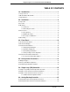
Single Loop Process Controller Instruction Manual TABLE OF CONTENTS 1.0 - Introduction .......................................................................... 1 1.1 Scope of Book ............................................................................................... 1 1.2 Model Number Breakdown ............................................................................ 4 1.3 Specifications................................................................................................. 5 2.
Single Loop Process Controller Instruction Manual 6.3 Analog Backup Controller Parameter Selections ........................................ 70 6.3.1 Abbreviated Configuration Tables .................................................. 71 7.0 - Ratio (PID) Controller ........................................................ 75 7.1 Ratio (PID) Controller Operation Overview ................................................. 75 7.2 Ratio (PID) Controller Front Panel Pushbuttons...................................
Single Loop Process Controller Instruction Manual B.1 Standard Communications ........................................................................ 125 B.1.1 Configuration................................................................................ 126 B.1.2 Protocol........................................................................................ 127 B.1.3 Message Types............................................................................ 128 B.1.4 Communication Transaction Examples.....
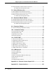
Single Loop Process Controller Instruction Manual LIST OF FIGURES Figure 1-1. Information Layout of Book .............................................................. 3 Figure 2-1. Outline Dimensions and Panel Cut-Out Requirements .................. 11 Figure 2-2. Single or Multiple Panel Mounting .................................................. 12 Figure 2-3. Intercase Spacing ........................................................................... 12 Figure 2-4.
Single Loop Process Controller Instruction Manual Figure 8-3. Automatic/Manual Station Push Buttons ........................................ 87 Figure 8-4. CS4 Datapoint Selections .............................................................. 90 Figure 9-1. Parameter Display Edit Function .................................................... 96 Figure 9-2. Parameter Display Datapoint Selections ........................................ 97 Figure 10-1. Typical Step Response Method ...........................
Single Loop Process Controller Instruction Manual Table 5-6. Controller Module (CON-0)............................................................. 62 Table 5-7. Communication Module .................................................................. 63 Table 5-8. System Module ............................................................................... 63 Table 6-1. Analog Backup Controller Pushbutton Functions ............................ 68 Table 6-2. Analog lnput (ANI) Module.........................
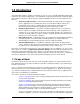
Single Loop Process Controller Instruction Manual 1.0 Introduction The 53SL5100 Controller is capable of functioning as any one of four selectable application-specific (AS) instruments. The instrument application is selected with the front panel push buttons by entering the appropriate number (1 through 4 respectively) into a designated database location. The four instrument selections are: 1.
Single Loop Process Controller Instruction Manual parameters in tables, by function. • Section 5, Single Loop (PID) Controller, Section 6, Analog Backup Controller, Section 7, Ratio (PID) Controller, Section 8, Automatic/Manual Station Sections 5, 6, 7 and 8 use the same structure for presentation, but differ in content.
Single Loop Process Controller Instruction Manual Figure 1-1.
Single Loop Process Controller Instruction Manual 1.2 Model Number Breakdown Refer to the MicroMod data sheet or data tag for the model number of the product furnished.
Single Loop Process Controller Instruction Manual 1.3 Specifications Table 1-1. Specifications Item Specification(s) Power Requirements (as specified) 22 - 26 V dc 108-132 V rms 216 - 264 V rms 50/60 Hz Power Consumption (AC/DC operation) 36 VA maximum Internal Power Supply: Available Power Output for Transmitters 25 V dc ± 1 V dc @ 80 mA maximum, short circuit protected.
Single Loop Process Controller Instruction Manual Table 1-1. Specifications (Continued) Item Specification(s) Analog Output (ANO0) Signal (is referenced to power common) 1 (ANO0) Quantity Signal Range 0 - 20 mA DC (4 - 20 mA dc typically) Load Range 0 - 750 ohms Accuracy ± 0.
Single Loop Process Controller Instruction Manual Table 1-1. Specifications (Continued) Item Environmental Characteristics (Cont’d): Transient Immunity (all circuits) Specification(s) ANSI C37.90a - 1974/IEEE Std 472- 974: Ring Wave: 1.5 MHz, 3 kV, 60 pulses/s for 2.0 s EMI Susceptibility SAMA PMC 33.1-1978: Class 3-abc: no effect at 30 V/m, at 27, 146, and 446 MHz Enclosure Classification/Environment Panel Mounted Equipment: No enclosure rating.
Single Loop Process Controller Instruction Manual Table 1-1. Specifications (Continued) Item 8 Specification(s) Physical Characteristics Material of Construction: Case Steel, black enamel Circuit Boards Glass epoxy Bezel ULTEM 1000 (Polyethermide Resin) Flammability-UL94 5V Dimensions 2.844W x 5.656H x 12.906L (inches) 73W x 144H x 329L (mm) Flush Panel Mounting 0.125 inch - 1 inch thickness (3.2 mm - 25.
Single Loop Process Controller Instruction Manual 2.0 Installation 2.1 Inspection An itemized list of all items in the shipment is attached to the shipping container. Inspect the equipment upon arrival for damage that may have occurred during shipment. All damage claims should be reported to the responsible shipping agent before installation is attempted. If damage is such that faulty operation is likely to result, the MicroMod Service Department should be notified.
Single Loop Process Controller Instruction Manual frames) are available in various sizes and are supplied to conform with the particular panel cut-out. ✎ Note Mounting brackets and trim collars (mounting frames) are packaged separately. Check the shipment carefully to prevent loss of mounting hardware. To install single or multiple mounted instruments in a prepared panel cut-out, proceed as follows. 1. Remove the through-case shipping bolt. 2.
Single Loop Process Controller Instruction Manual Figure 2-1.
Single Loop Process Controller Instruction Manual Figure 2-2. Single or Multiple Panel Mounting Figure 2-3.
Single Loop Process Controller Instruction Manual 2.4 Connections 2.4.1 Preparatory The 53SL5100A can be configured as a Single Loop Controller, Analog Backup Controller, Ratio Controller, or an Automatic/Manual Station. Therefore, prior to electrical interconnection, the particular instrument configuration should be determined with all assigned inputs and outputs identified to assure proper signal routing. 2.4.
Single Loop Process Controller Instruction Manual ✎ Note Use of a common bus bar is recommended to minimize potential voltage differences that may occur as the result of ground current loops, e.g., potential difference between separate signal grounds, power grounds, etc. 2.4.2.1.2 AC Power Reference Figure 2-4 and connect the specified line service (110-120, 220-240 V ac, 50 or 60 Hz) to the controller, as follows: 1.
Single Loop Process Controller Instruction Manual The contact output is assigned and used depending on the controller configured mode of operation. When this contact is connected to an inductive load, an external arc suppression network is required for contact protection. 2.4.2.6 Datalink Connections Datalink is an interrogator/responder serial interface capable of supporting 32 instruments on a single network. It uses an RS485 physical interface.
Single Loop Process Controller Instruction Manual Figure 2-4.
Single Loop Process Controller Instruction Manual Figure 2-5.
Single Loop Process Controller Instruction Manual 18 Installation
Single Loop Process Controller Instruction Manual 3.0 Front Panel 3.1 Front Panel Introduction The front panel of the instrument contains the display and all push buttons used to change display presentations and parameters. The front panel has a gas discharge 96 X 48 dot matrix display, a six pushbutton vertical keypad, and a four pushbutton horizontal keypad. It also has a configuration port DIN plug, which is concealed behind the identification tag pull-down door.
Single Loop Process Controller Instruction Manual selectable parameter display. Although the contents of the parameter display are selectable configuration items, the display format is identical for each of the four control strategies. Any display type can have a portion of its contents overlaid with an ALARM indicator. If the instrument is manually set to engineering mode, the display can be overlaid with the CONFIGURATION or DISPLAY data entry line.
Single Loop Process Controller Instruction Manual Figure 3-3. CS3, Ratio Controller Figure 3-4.
Single Loop Process Controller Instruction Manual Figure 3-5. CS1 - CS4 Parameter Display Figure 3-6.
Single Loop Process Controller Instruction Manual Figure 3-7. Configure Overlay 3.3 Front Panel Pushbuttons The front panel pushbuttons are used to vary the display presentation, to select instrument operator or engineering modes, and to select local or remote setpoint levels. In engineering mode, (EMODE) they are also used to display and/or alter database parameters which are presented as single line datapoints in the configuration overlay.
Single Loop Process Controller Instruction Manual strategy. These differences are included as part of the push button descriptions provided in each individual control strategy section of the book. Figure 3-8.
Single Loop Process Controller Instruction Manual Table 3-1. Pushbutton Functions Pushbutton R/L Title Remote/Local Select Operator Mode Engineering Mode This pushbutton is used to select between Remote setpoint control and Local setpoint control. When in Remote, an R appears in the lower right of the display. When in Local, an L appears in the lower right of the display. ↑ Setpoint Increase The setpoint indicator increases (EMODE Character (rises) when this pushbutton is Select) pressed and held.
Single Loop Process Controller Instruction Manual Table 3-1. Pushbutton Functions (Continued) Pushbutton A/M Operator Mode Engineering Mode Auto/Manual Select This pushbutton is the Auto/ Manual mode toggle. When toggled to Auto, an A appears before the R or L (for Remote or Local), in the lower middle right of the display. When toggled to Manual, an M appears before the R or L (for Remote or Local), in the lower right of the display. Auto indicates the process is under instrument control.
Single Loop Process Controller Instruction Manual Table 3-1. Pushbutton Functions (Continued) Pushbutton Title F3 (EMODE ENTER key) ● Mode Select/Alarm Reset Operator Mode Engineering Mode In the configuration function, pressing this pushbutton causes the addressed datapoint to be altered with the character string that was entered with the EMODE Cursor Control and Character Select pushbuttons. In display function, pressing this pushbutton causes the addressed datapoint to display its contents.
Single Loop Process Controller Instruction Manual 3.3.1 Displaying a Datapoint The following procedure illustrates how to enter EMODE and use the display function to access the contents of datapoint A001 (A1). The displayed contents will be PERCENT. Figure 3-9 and Figure 3-10 are supporting illustrations for the display procedure which is described in Table 3-2. It should be noted that EMODE has a 20 second timeout if it is accessed and its functions (e.g., configure or display) are not used. Table 3-2.
Single Loop Process Controller Instruction Manual Figure 3-10. A1 PERCENT 3.3.2 Altering a Datapoint The following procedure illustrates how to enter EMODE and use the configuration function to alter the contents of datapoint B000 (B0) with a 97. Entering a 97 in B00 invokes the display test which strobes the display matrix dots on and off at 5 second intervals (approximate). When off, a perimeter of dots still remains lit.
Single Loop Process Controller Instruction Manual Table 3-3. Procedures to Alter a Datapoint (Continued) Step Press 12 13 Shift Press to Result Locate Target Char. Result To stop test, change B00 contents from 97 to 00 (Instrument Suspend State). MODE Returns instrument to operator mode. Note: ∆ = space. Figure 3-11. Checkerboard Pattern Figure 3-12.
Single Loop Process Controller Instruction Manual 3.3.3 Defaulting the Database Defaulting the database sets all non-instrument-specific datapoint parameters to predetermined values, then suspends the instrument which is indicated by the logo presented on the display. When instrument operation is suspended, instrument algorithmic control ceases. The procedure to default the database is presented in Table 3-4 and the display logo is illustrated in Figure 3-13.
Single Loop Process Controller Instruction Manual Table 3-4. Defaulting the Database (Continued) Step Press 8 hold→ Shift Press to Result Locate ← 11 F3 12 MODE Note: ∆ = space. 32 Front Panel .9∆ Result B00 contents shifted right; only locator point remains on the entry line: B00 . . locator 9 10 Target Char. ↑ 9 Puts 9 on entry line: B00 .9. ↑ 8 Shifts 9 and puts 8 on entry line: B00 .98. Enters 98 in B00 to default the database. Returns instrument to operator mode.
Single Loop Process Controller Instruction Manual 3.3.4 Responding to the Prompt KEY? When the password prompt KEY? appears, it indicates a password was set with an external device (e.g., Hand-Held Configurer, PC, etc.). The password can not be set via the front panel keys. A password key is a maximum of 10 numeric characters (numbers 0-9 only). It does not impede display functions in EMODE but must be unlocked to perform configuration functions.
Single Loop Process Controller Instruction Manual Figure 3-14 illustrates the KEY? prompt. Figure 3-14. The KEY? Prompt 3.4 Front Panel Pushbutton Alternatives There are four alternative methods other than the front panel push buttons for accessing and changing database parameters. All four methods to display and/or alter database parameters are listed as follows: 1. Using an IBM PC compatible computer running the MC5FIG.EXE configuration program that is supplied as part of the 53HC3300 software package.
Single Loop Process Controller Instruction Manual PC communications connector. Figure 3-15.
Single Loop Process Controller Instruction Manual 3.4.1 Using the Hand-Held Configurer The Hand-Held Configurer (HHC) is a portable terminal designed to interface with the instrument through the configuration port that is located behind the pull-down door on the front panel of the instrument (see Figure 3-1). The HHC is available in two versions: 1. A Standard HHC with capabilities to display or alter specifically addressed parameters in the instrument database.
Single Loop Process Controller Instruction Manual 3.4.1.2 Displaying a Database Parameter To display a database parameter, press D and enter the parameter ID, then press ENTER. The current value of the parameter is displayed. The parameter ID is the data type identifier (B, L, C, H, F, and A) and point number as described in Figure 4-1 in Section 4. For example, to display the value of datapoint B12, press: D B12 The value presently assigned to B12 is displayed.
Single Loop Process Controller Instruction Manual up to 10 characters because instrument front panel password entry permits only numbers (0-9) as KEY? input characters. To remove a password key completely, press CTRL 0 (hold CTRL and press 0), then ENTER. 3.4.1.5 Storage Cartridge Transfer The procedure for saving or loading the database or calibration constants of an instrument to/from a storage cartridge is as follows: 1. Insert the cartridge containing the desired database in the HHC.
Single Loop Process Controller Instruction Manual 3.4.1.6 Sample Hand-Held Configurer Commands Table 3-6 provides a sample of typical Hand-Held Configurer Display (D), Put (P), and Memory Transfer (T) commands. Table 3-6. Typical HHC Commands Key Entries Displayed Data Result D B001 D B001 XXX Displays contents of B001. D N D B002 XXX Displays contents of B002. D D B002 XXX B002 contents still displayed.
Single Loop Process Controller Instruction Manual 40 Front Panel
Single Loop Process Controller Instruction Manual 4.0 Configuration Parameters The configuration parameters provide the latitude to define the instrument’s personality attributes, so that while still functioning within its designed specifications, it can perform application requirements with greater refinement.
Single Loop Process Controller Instruction Manual 4.2 Factory Standard Configuration The instrument is shipped from the factory configured as summarized in Table 4-2. Table 4-2. Factory Standard Configuration Datapoint Value Attribute B000 1 C106 100 C107 0 No Reset (TR) action. C108 0 No Derivative (TD) action. B335 1 No Alarms. C256 100 L416 0 ANI0 Input Voltage Range is 1 - 5 V. L106 1 Reverse Switch is set so that the instrument output decreases as PV increases.
Single Loop Process Controller Instruction Manual 4.3 Configuring the Database Modules The datapoints in the database modules must be changed to reflect required alterations in the factory standard configuration or when the instrument is re-configured. There are generally four datapoint parameter types contained in the eight database modules. The parameter types affect Datalink communications, display indications, input-output signals, and instrument responsiveness.
Single Loop Process Controller Instruction Manual Table 4-4. Analog Input Module Title Symbol ANI0 Datapoint ANI1 Datapoint Default Attributes Purpose: This module is used to configure input voltage characteristics (e.g., input voltage range), and how the input signal is interpreted (linear or square root representation). Analog Input (Display Only) ANI H000 H001 0 This is the value in engineering units of the measured input after all signal conditioning has been applied.
Single Loop Process Controller Instruction Manual Table 4-4. Analog Input Module (Continued) Symbol ANI0 Datapoint ANI1 Datapoint Tag Name AITAG A224 A225 Engineering Units AIEU A298 A299 Title Default ANI0 ANI1 Attributes It is an assignable 10 character name for the analog input (ANI0, ANI1). Percent It is assignable for units of measure the ANI represents (e.g., GPM for gallons/ minute). Figure 4-1. ANIO/1 Figure 4-2.
Single Loop Process Controller Instruction Manual Table 4-5. Analog Output Module Title Symbol ANO0 Datapoint Default Attribute Purpose: The primary purpose of this module is to set the 0 - 20 mA output signal relative to the displayed percent out. Analog Output (Display Only) ANO C000 0 The value in this datapoint represents the percent of output to be generated by hardware (e.g., 100% output = 20 mA). OZBASE L472 0 When a 0, the percentage output generates a 4 - 20 mA signal.
Single Loop Process Controller Instruction Manual Figure 4-3. CCI0 Figure 4-4. CCO0 ✎ Notes WD = Watchdog These figures are graphical representations of the signal conditioning that occurs on the instrument main board. They are provided for reference purposes only.
Single Loop Process Controller Instruction Manual Table 4-7. Contact Output Module (CCO) Title Symbol CCO0 Datapoint Default Attribute Purpose: This module allows the action of the CCO to be reversed (normally a closed contact =1, but can be changed to = 0). Contact Output (Display Only) CCO L024 0 If CCO = 0 and OINV = 0, then it is open. If CCO = 0 and OINV = 1, then it is closed. If CCO = 1 and OINV = 0, then it is closed. If CCO = 1 and OINV = 1, then it is open.
Single Loop Process Controller Instruction Manual Table 4-8. Controller Module (CON-0) CS CON-0 Symbol ■ ● ▲ ◆ Default Datapoint 1|2|3|4 Title Attribute Purpose: The primary purpose of this module is to set the instrument’s responsiveness, Alarm Limits 1 & 2, Alarm Dead Band, and the range limits (e.g., 0 - 100, -20 - 80, etc.). Note: ■ ● ▲ ◆ = applicable to the Control Strategy (CS) as shown in column three.
Single Loop Process Controller Instruction Manual Table 4-8. Controller Module (CON-0) (Continued) Title CS CON-0 Symbol ■ ● ▲ ◆ Default Datapoint 1|2|3|4 Attribute Reverse Valve RSV ■ ● ▲ u L109 0 This parameter provides information for the control display to indicate which direction the control output must go to close the final control element. A 1 indicates that 20 mA closes the valve. A 0 indicates that 20 mA opens the valve.
Single Loop Process Controller Instruction Manual Table 4-8. Controller Module (CON-0) (Continued) Title CS CON-0 Symbol ■ ● ▲ ◆ Default Datapoint 1|2|3|4 Controller Span ■ ● ▲◆ C115 100 Controller Lower Range ■ ● ▲◆ C116 0 Control Tag Name ■ ● ▲◆ A000 CON0 Engineering Units ■ ● ▲◆ A001 Attribute These two parameters set the upper and lower values on the controller display. They permit the control action to be defined over a range independent of the process variable input range.
Single Loop Process Controller Instruction Manual Table 4-9. Parameter Display Module (Continued) Title Symbol PAR1 Default Attribute Point 3 Designator PDC F089 C108 value A database datapoint whose contents will be displayed under the Point 3 Name (e.g., C105 to display the Alarm Dead Band). Modify Disable PMD L313 0 When this value is 1, the datapoints in this module can not be altered with the pushbuttons. The values of these datapoints are only for display purposes.
Single Loop Process Controller Instruction Manual Table 4-10. Communication Module (Continued) Symbol CCO0 Datapoint Default Attribute No Byte Stuffing CB L2581 0 When set to a 1, this datapoint disables the standard MicroMod communication protocol feature which inserts a 00 (NUL) byte after every 7EH (SOH) that is not the beginning of a message. (This permits user-written communications software to determine the number of bytes to expect in a response message.
Single Loop Process Controller Instruction Manual 54 Configuration Parameters
Single Loop Process Controller Instruction Manual 5.0 Single Loop (PID) Controller 5.1 Single Loop (PID) Controller Operation Overview In a standard feedback control loop, the Single Loop (PID) Controller functions as the primary processing unit. When the process is altered due to disturbances (e.g., flow rate changes), the controller gauges this change from the process variable (PV) feedback signal sent to it by a process measurement instrument (e.g., flow meter) in the loop.
Single Loop Process Controller Instruction Manual to the final element to restore the process. The output signal (Analog Output) to the final element is 4-20 mA dc. This signal is also factory calibrated for zero and span, and should not be altered. On the controller display, the output signal value correlates to the desired control element operation (e.g.
Single Loop Process Controller Instruction Manual 5.2 Single Loop Controller Front Panel Pushbuttons The front panel pushbuttons for the Single Loop Controller are illustrated in Figure 5-3 and defined in Table 5-1. The pushbutton functions for the Single Loop Controller are identical to those provided in Section 3. Figure 5-3.
Single Loop Process Controller Instruction Manual This push button is the Auto/Manual mode toggle. When toggled to Auto, an A appears before the R or L Table 5-1. Single Loop Controller Pushbutton Functions Button R/L 58 Title Remote/Local Select Operator Mode Engineering Mode This push button is used to select between Remote setpoint control and Local setpoint control. When in Remote, an R appears in the lower right of the display. When in Local, an L appears in the lower right of the display.
Single Loop Process Controller Instruction Manual Table 5-1. Single Loop Controller Pushbutton Functions Button Title Operator Mode Engineering Mode ← Output Decrease (EMODE Cursor Control) The output indicator decreases when this pushbutton is pressed and held. Release the pushbutton when the desired output level is reached. This pushbutton is for Manual operation only. For configure or display functions, the cursor shifts one position to the left each time this pushbutton is pressed.
Single Loop Process Controller Instruction Manual 5.3 Single Loop Controller Parameter Selections Figure 5-4 illustrates how a Single Loop Controller would appear with only the default values and power applied, but no analog input or output signals. In Figure 5-5, ANO0 (TB1-10) is jumpered to ANI0 (TB1-2) to simulate process operation. The unit has the AC power supply and power cord 173D109U03. Connecting ANO0 to ANI0 is done only for illustration purposes and is not necessary to configure the controller.
Single Loop Process Controller Instruction Manual 5.3.1 Abbreviated Configuration Tables Table 5-1 through Table 5-8 are provided as a quick reference source for the contiguration datapoints. These tables do not have the definition column; therefore, for the initial instrument configuration, Section 4 should be referenced until each datapoint functionality can be recognized by its title.
Single Loop Process Controller Instruction Manual . Table 5-4. Contact Input Module (CCI) Symbol CCI Datapoint Default Contact Input (Display Only) CCI L000 0 Contact Input Invert IINV L264 0 CITAG A262 CCI0 Title Tag Name . Table 5-5. Contact Output (CCO) Module Title Symbol CCO0 Datapoint Default Contact Output (Display Only) CCO L024 0 Contact Output Invert OINV L288 0 COTAG A280 CCO0 Tag Name Table 5-6.
Single Loop Process Controller Instruction Manual Table 5-6. Controller Module (CON-0) (Continued) Symbol CON-0 Datapoint Default Manual Reset MR C111 50 Controller Span IR C115 100 Controller Lower Range ILR C116 0 Control Tag Name CTAG A000 CON-0 Engineering Units CEU A001 Percent Title Table 5-7.
Single Loop Process Controller Instruction Manual 64 Single Loop (PID) Controller
Single Loop Process Controller Instruction Manual 6.0 Analog Backup Controller 6.1 Analog Backup Controller Operation Overview The Analog Backup Controller is used in operations where a remote computer is normally controlling the final element directly. In this process configuration, the controller functions as a signal selector and automatic backup unit to the computer. The controller assumes process control in the event of a signaled computer failure.
Single Loop Process Controller Instruction Manual 1. ANI0 = Process Variable 2. ANI1 = Control Element Feedback 3. ANO0 ~ Controller Output 4. CCI0 = Computer Ready 5. CCO0 = Computer Output Diverter 6. CCO1 = Backup Output Diverter Figure 6-2.
Single Loop Process Controller Instruction Manual 6.2 Analog Backup Controller Front Panel Pushbuttons The front panel push buttons for the Analog Backup Controller are illustrated in Figure 6-3 and defined in Table 6-1. Figure 6-3.
Single Loop Process Controller Instruction Manual Table 6-1. Analog Backup Controller Pushbutton Functions Button R/L R/Local Select Operator Mode Engineering Mode This pushbutton is used to select between computer process control (R) or controller process control (Local). When in computer process control, an R appears in the lower right of the display. When in Local, an L appears in lower right of the display.
Single Loop Process Controller Instruction Manual Table 6-1. Analog Backup Controller Pushbutton Functions Button Operator Mode Engineering Mode Output Increase (EMODE Cursor Control) The output indicator increases when this pushbutton is pressed and held. Release the pushbutton when the desired output level is reached. This pushbutton is for Manual operation only when the controller is in Local.
Single Loop Process Controller Instruction Manual 6.3 Analog Backup Controller Parameter Selections Figure 6-4 illustrates how an Analog Backup Controller would appear with only the default values and power applied., but no analog input or output signals. In Figure 6-4, ANO0 (TB1-10) is jumpered to ANI0 (TB1-2) to simulate process operation. The unit has the AC power supply and power cord 173D109U03.
Single Loop Process Controller Instruction Manual 6.3.1 Abbreviated Configuration Tables Table 6-2 through Table 6-8 are provided as a quick reference source for the configuration datapoints. These tables do not have the definition column; therefore, for the initial instrument configuration, Section 4 should be referenced until each datapoint functionality can be recognized by its title.
Single Loop Process Controller Instruction Manual . Table 6-4. Contact Input Module (CCI) Symbol CCI Datapoint Default Contact Input (Display Only) CCI L000 0 Contact Input Invert IINV L264 0 CITAG A262 CCI0 Title Tag Name Table 6-5.
Single Loop Process Controller Instruction Manual Table 6-6. Controller Module (CON-0) (Continued) Symbol CON-0 Datapoint Default Rate Time TD C108 0 Manual Reset MR C111 50 Controller Span IR C115 100 Controller Lower Range ILR C116 0 Control Tag Name CTAG A000 CON-0 Engineering Units CEU A001 Percent Title Table 6-7.
Single Loop Process Controller Instruction Manual 74 Analog Backup Controller
Single Loop Process Controller Instruction Manual 7.0 Ratio (PID) Controller 7.1 Ratio (PID) Controller Operation Overview The Ratio (PID) Controller is used where one variable, called the controlled variable, must be automatically maintained in definite proportion to another variable, called the wild variable. Transmitting meters (e.g., flow meters) must be installed in each variable line.
Single Loop Process Controller Instruction Manual ✎ Procedure Note To minimize sudden process changes, adjust the local setpoint value to cause the setpoint pointer to cover the ratio tick bar before switching to ratio control (Ratio). As illustrated in Figure 7-2, Ratio (PID) Controller Block Diagram, when a 3 is loaded into System Module datapoint B00 to indicate CS3, the signal designators are as follows: 1. ANI0 = Controlled Variable 2. ANI1 = Wild Variable 3. ANO0 = Controller Output 4.
Single Loop Process Controller Instruction Manual 7.2 Ratio (PID) Controller Front Panel Pushbuttons The front panel push buttons for the Ratio (PID) Controller are illustrated in Figure 7-3 and defined in Table 7-1. Figure 7-3.
Single Loop Process Controller Instruction Manual Table 7-1. Ratio (PID) Controller Pushbutton Functions Button Title Operator Mode Engineering Mode Ratio/Local Select R indicates Ratio control whereby the controller maintains a set proportion between the wild variable line and the controlled variable line. When in Ratio, an R appears in the lower right of the display. When in Local, an L appears in the lower right of the display.
Single Loop Process Controller Instruction Manual Table 7-1. Ratio (PID) Controller Pushbutton Functions Button → F1, F2 Title Operator Mode Engineering Mode Output Increase (EMODE Cursor Control) The output indicator increases when this pushbutton is pressed and held. Release the pushbutton when the desired output level is reached. This pushbutton is for Manual operation only. For configure or display functions, the cursor shifts one position to the right each time this pushbutton is pressed.
Single Loop Process Controller Instruction Manual 7.3 Ratio Controller Parameter Selections Figure 7-4 illustrates how a Ratio Controller would appear with only the default values and power applied, but no analog input or output signals. In Figure 7-4, ANO0 (TB1-10) is jumpered to ANI0 (TB1-2) to simulate process operation. The unit has the AC power supply and power cord 173D109U03. Connecting ANO0 to ANI0 is done only for illustration purposes and is not necessary to configure the controller.
Single Loop Process Controller Instruction Manual 7.3.1 Abbreviated Configuration Tables Table 7-2 through Table 7-7 are provided as a quick reference source for the configuration datapoints. These tables do not have the definition column; therefore, for the initial instrument configuration, Section 4 should be referenced until each datapoint functionality can be recognized by its title.
Single Loop Process Controller Instruction Manual Table 7-4. Contact Output (CCO) Module Title Symbol CCO0 Datapoint Default Contact Output (Display Only) CCO L024 0 Contact Output Invert OINV L288 0 COTAG A280 CCO0 Tag Name Table 7-5.
Single Loop Process Controller Instruction Manual Table 7-6. Communication Module Title Symbol Datapoint Default Instrument Address IA B01 0 Baud Rate BR B02 253 No Parity CP L256 0 No Byte Stuffing CB L258 0 Datalink Disable DLD L257 0 Table 7-7.
Single Loop Process Controller Instruction Manual 84 Ratio PID Controller
Single Loop Process Controller Instruction Manual 8.0 Automatic/Manual Station 8.1 Automatic/Manual Station Operation Overview The Automatic/Manual Station is a conventional single station selector. In Auto, the auto input (Analog Input 0) is passed directly through the station to the output (Analog Output 0). In Manual, the station functions as a manual loader, allowing the output to be controlled from the front panel pushbuttons.
Single Loop Process Controller Instruction Manual Figure 8-2.
Single Loop Process Controller Instruction Manual 8.2 Automatic/Manual Station Front Panel Pushbuttons The front panel push buttons for the Automatic/Manual Station are illustrated in Figure 8-3 and defined in Table 8-1. Figure 8-3.
Single Loop Process Controller Instruction Manual Table 8-1. Automatic/Manual Station Pushbutton Functions Button Title R/L Ratio/Local Select (not used) ↑ Setpoint Increase (not used) Operator Mode For configure or display functions, the character set displays one character at a time in ascending alphanumeric order when this pushbutton is pressed and held. Release the pushbutton when the desired character, number, or symbol appears.
Single Loop Process Controller Instruction Manual Table 8-1. Automatic/Manual Station Pushbutton Functions (Continued) Button → F1, F2 Title Operator Mode Engineering Mode Output Increase (EMODE Cursor Control) The output indicator increases when this pushbutton is pressed and held. Release the pushbutton when the desired output level is reached. This pushbutton is for Manual operation only.
Single Loop Process Controller Instruction Manual 8.3 Automatic/Manual Station Parameter Selections Figure 8-4 illustrates how a Single Loop Controller might appear with only the default values and power applied, but no analog input or output signals. In Figure 8-4, ANO0 (TB1-lO) is jumpered to ANI0 (TB1-2) to simulate process operation. The unit has the AC power supply and power cord 173D109U03.
Single Loop Process Controller Instruction Manual 8.3.1 Abbreviated Configuration Tables Table 8-2 through Table 8-8 are provided as a quick reference source for the configuration datapoints. These tables do not have the definition column; therefore, for the initial instrument configuration, Section 8 should be referenced until each datapoint functionality can be recognized by its title.
Single Loop Process Controller Instruction Manual . . Table 8-4. Contact Input Module (CCI) Symbol CCI Datapoint Default Contact Input (Display Only) CCI L000 0 Contact Input Invert IINV L264 0 CITAG A262 CCI0 Title Tag Name Table 8-5. Contact Output (CCO) Module Title Symbol CCO0 Datapoint Default Contact Output (Display Only) CCO L024 0 Contact Output Invert OINV L288 0 COTAG A280 CCO0 Tag Name Table 8-6.
Single Loop Process Controller Instruction Manual Table 8-7. Communication Module Title Symbol Datapoint Default Instrument Address IA B01 0 Baud Rate BR B02 253 No Parity CP L256 0 No Byte Stuffing CB L258 0 Datalink Disable DLD L257 0 Table 8-8.
Single Loop Process Controller Instruction Manual 94 Automatic/Manual Station
Single Loop Process Controller Instruction Manual 9.0 Parameter Display The parameter display can be accessed from any control strategy (CS1 - CS4) by pressing the F1 or F2 front panel push button. It provides convenient access to view and/or alter three parameter datapoint values that were selected when the display was configured. (The option to view and alter any parameter datapoint value with EMODE is still available.
Single Loop Process Controller Instruction Manual Figure 9-1.
Single Loop Process Controller Instruction Manual 9.1 Parameter Display Configuration Settings Figure 9-2 is an illustration of the parmeter display with datapoint call outs. Table 9-2 is an abbreviated parameter display configuration table. Figure 9-2. Parameter Display Datapoint Selections Table 9-2. Parameter Display Module Title Symbol PAR1 Default PTAG A014 CON-0 Tune Point 1 Name PNA A015 Prop.
Single Loop Process Controller Instruction Manual 98 Parameter Display
Single Loop Process Controller Instruction Manual 10.0 Instrument Tuning Tuning the instrument is an iterative process to refine the Proportional Band (PB), Integral (also called Reset Time [TRI]), and Derivative (TD) parameters of the Control Module 0 (CON-0). The three parameter datapoints are C106, Proportional Band (PB); C107, Reset Time (TR); and C108, Derivative Time (TD).
Single Loop Process Controller Instruction Manual 10.3 Derivative Action (TD) Derivative action augments proportional action by responding to the rate of change of the process variable. It is used to make the controller more responsive to sudden process disturbances. The datapoint to set the Rate parameter is C108; it has a default value of 0 minutes. The minimum value for derivative action is 0.01 minutes and the maximum time is 8 minutes; 0 is off.
Single Loop Process Controller Instruction Manual Table 10-2. Trial and Error Tuning Method (Continued) Step Procedure 12 lntroduce automatic reset slowly by decreasing TR (C107) until cycling starts. 13 Back off TR (C107) to a safe margin of about 1.5 times the value attained in Step 12. Table 10-3. Proportional Cycle Method Step Procedure 1 Set the process to approximately normal conditions in Manual mode. 2 Set TR (C107) first to minimum value (0.
Single Loop Process Controller Instruction Manual Table 10-4. Step Response Method Step Procedure 1 Set the process to approximately normal conditions in Manual mode. 2 Introduce a 10% (approximate) step change to the manually regulated signal to the valve. Observe the magnitude of the step in percent of full signal span F. Also plot a graph of the resulting transient curve traced by the controlled variable.
Single Loop Process Controller Instruction Manual 11.0 EASY-TUNE The EASY-TUNE algorithm is used to help determine the optimal tuning values for the Proportional Band (PB), Integral (TR), and Derivative (TD) parameters (called PID constants) in the Controller Module Mode 0 (CON-0). The three parameter datapoints are C106, Proportional Band (PB); C107, Reset Time (TR); and C108, Derivative Time (TD).
Single Loop Process Controller Instruction Manual 11.3 EASY-TUNE Parameters All pertinent input parameters to the EASY-TUNE algorithm are obtained from Controller Module Mode 0, which must first be configured. The parameters that must be configured before initiating the EASY-TUNE sequence (B008 = 1) are items 1, 3, 5 through 10, in Table 11-1. Table 11-1.
Single Loop Process Controller Instruction Manual Table 11-1. EASY-TUNE Parameters (Continued) Item Datapoints C382 C383 C384 Modifiers to Tuning Criteria (see Section 11.5.) TP Time Constant modifier KP Process Gain modifier WP Dead-Time modifier C391 C392 C393 C394 C395 C396 EASY-TUNE Results (display only): TP Time Constant (seconds) KP ProcessGain WP Dead-Time (seconds) % PB TR (minutes) TD (minutes) 11 12 Default Value Description 0.1 0.1 0.
Single Loop Process Controller Instruction Manual 11.4 EASY-TUNE Sequence Status Once initiated, the algorithm sets the instrument to Manual mode. After a period of settling time, a step change in instrument output is applied and the resulting process response is observed. As summarized in Table 11-2 and Table 11-3, datapoint 8387, EASY-TUNE Status, will numerically show the result of the EASY-TUNE algorithm. Figure 11-1 illustrates this event sequence and correlates it to the numeric codes in B387.
Single Loop Process Controller Instruction Manual Table 11-3. EASY-TUNE Unsuccessful Status Display (Continued) Step Procedure Suggested Action/Cause/Retry 60 Abort EASY-TUNE Switch, L521 was set to 1. EASY-TUNE was aborted. 61 Tuning parameter limits were exceeded and used in the instrument. Widen the tuning parameter limits in C385 C390 or set Enable Tuning Parameter Limits, L520 to 0.
Single Loop Process Controller Instruction Manual Figure 11-1.
Single Loop Process Controller Instruction Manual 11.5 Modifications to Tuning Criteria During EASY-TUNE sequence execution, each of the three algorithm variables: Time Constant (TP ), Process Gain (KP), and Dead-Time (WP), are altered by 10% in the conservative direction, (instrument operating characteristics would be slower response, but less chance of oscillation and instability) before the tuning parameters are computed using the ITAE equations listed in Table 11-4.
Single Loop Process Controller Instruction Manual Figure 11-2.
Single Loop Process Controller Instruction Manual 11.6 Aborting the EASY-TUNE Sequence If the EASY-TUNE sequence is active and the instrument output is deliberately changed, the sequence will be aborted. The original instrument output and Manual or Auto mode will be restored. Datapoint B387, EASY-TUNE Status, will be set to 54. If the EASY-TUNE sequence is active and datapoint L521, EASY-TUNE Abort Switch, is set to 1, the sequence is immediately aborted.
Single Loop Process Controller Instruction Manual 112 Easy-Tune
Single Loop Process Controller Instruction Manual 12.0 Maintenance ✎ Note The factory set calibration constants for ANI0, ANI1, and ANO0 are applicable only for the main printed circuit board supplied in the particular controller. This data is recorded on a calibration sheet supplied with the controller. The data should be retained to facilitate easy field recalibration in the event one or more of the constants is inadvertently changed. 12.
Single Loop Process Controller Instruction Manual To remove the main PCB: 1. Use the PCB’s front edge board ejector to pull it free from the rear terminal board slot, and carefully slide it from the case. 2. Disconnect the front display panel flat ribbon cable from the main PCB. To install the replacement main PCB: 1. Connect the front display panel ribbon cable. 2. Slide the PCB into the instrument case, seating it into the rear terminal board slot. 3. Install the front display panel.
Single Loop Process Controller Instruction Manual 12.4 Error and Hardware Malfunction Messages Error Messages: • LOGO - The controller is in the suspend state (also called FIX 0 because datapoint location B00 = 0). Hardware Malfunction Messages: · • Entire Display Flashes: The watchdog timer has timed out. • CPU RAM FAILURE: IC U1 is bad. • ROM CHKS FAILURE: IC U3 is bad. 12.5 Resetting the Controller The controller can be reset either by either of these methods: • Cycle the power.
Single Loop Process Controller Instruction Manual 12.6 Parts List The parts list is provided in Table 12-2 and the parts breakdown is illustrated in Figure 12-1. Table 12-2. Parts List Key Part Number Description 1 612B395U02 Case 2 686B689U01 Main Printed Circuit Board 3 164B130U03 Power Supply - 120/220/240 V ac, 50/60 Hz 164B130U04 Power Supply - 24 V dc Front Display 4 698B179U05/U063 5 686B598U01 Rear Terminal Board 6 677B942U01 Cable - Display to Main PCB 173D109U03 U.S.
Single Loop Process Controller Instruction Manual Figure 12-3 illustrates the pin assignments for the Communication ITB that is necessary for proper termination(s) of a Datalink network. Figure 12-1.
Single Loop Process Controller Instruction Manual Figure 12-2.
Single Loop Process Controller Instruction Manual Figure 12-3.
Single Loop Process Controller Instruction Manual 120 Maintenance
Single Loop Process Controller Instruction Manual Appendix A: Discrete Contact Output CCO The discrete output CCO is not a mechanical contact closure but an NPN Transistor that is analogous to a single pole, single throw switch with one terminal connected to power common. This circuit layout is commonly called an Open Collector Output. (See Figure A-1.) Capability limits of a CCO are as follows: • 50 mA maximum current flow when closed. • 30 V dc maximum tolerance voltage when open.
Single Loop Process Controller Instruction Manual Figure A-1. CCO Circuit and its Equivalent Figure A-2.
Single Loop Process Controller Instruction Manual Figure A-3. Operating CCOs in Parallel Figure A-4.
Single Loop Process Controller Instruction Manual Figure A-5.
Single Loop Process Controller Instruction Manual Appendix B: Communications B.1 Standard Communications Two digital communication channels are provided with this instrument: 1. There is a configuration port that is an RS-232 serial interface. It is accessed via a 5 pin mini-DIN connector located under the pull-down door on the front panel (see Figure 3-1). It is used to configure instrument parameters for selected operational characteristics.
Single Loop Process Controller Instruction Manual B.1.1 Configuration To initialize the instrument for binary communications, configure the instrument as described in Table B-1, Column 3 (Set Up). Table B-1. Communication Module Title Datapoint Set-Up Default Attribute Purpose: This module is used to configure the Datalink port parameters (e.g., baud rate, parity selection, etc.). Instrument Address B01 S 0 This item identifies the address of this instrument on the Datalink network.
Single Loop Process Controller Instruction Manual B.1.2 Protocol The Data link protocol requires the host or SUPERVISOR-PC to initiate alltransactions. There are two basic categories for all of the Datalink message types: • Interrogate, used to read data from an addressed instrument. • Change, used to alter a value in an addressed instrument. The addressed instrument decodes the message and provides an appropriate response.
Single Loop Process Controller Instruction Manual B.1.3 Message Types The types of messages that are sent between the host or SUPERVISOR-PC and the Datalink network instrument are formatted as follows: B.1.3.1 Host or SUPERVISOR-PC to Instrument: 1. INTERROGATE - This message requests up to 20H consecutively stored bytes, beginning at the specified memory address location of the addressed instrument. 01111110 EOH + I.A. NUM LO ADD HI ADD LRC 2.
Single Loop Process Controller Instruction Manual B.1.4.2 Transaction B Example Host or SUPERVISOR-PC sends two bytes of new data, to be loaded into the instrument at Datalink address 03, beginning at hexadecimal memory address 1000H. 1. Host sends CHANGE message. 01111110 10100011 00000010 00000000 00010000 00001000 00001100 11001001 SOH Command NUM + I.A. LO ADD HI ADD Data 1 Data 2 LRC 2. Instrument sends RESPONSE message.
Single Loop Process Controller Instruction Manual B.1.5 Calculating Data Addresses If communications software must be generated to accommodate unique Datalink applications requirements, then the instrument memory address scheme must be known for proper data bit (e.g., L data type) and data byte (e.g., B, C, H, and A data types) memory location determination. ✎ Note Numbers used in this section that are expressed in hexadecimal notation (base 16) are identified with an H after the number.
Single Loop Process Controller Instruction Manual Table B-3. Instrument Memory Address Scheme Data Type Base Memory Address Byte Size H F00H A (F)* 1400H Data Format Address Calculation Algorithm 5 Represents high precision floating point values that have a resolution of one part in 2 billion (31 bits) and a dynamic range of ± 1038. The first four bytes represent a 2’s complement notation in fractional form (2-n) whose absolute value is between 0.5 and 0.9999.
Single Loop Process Controller Instruction Manual B.1.6 Software Characteristics 1. Transparency Rule - whenever 7E hexadecimal is transmitted as anything other than SOH, a 00 byte will be inserted directly following it (byte stuffing). 2. All transactions are initiated by the Host or SUPERVISOR-PC. 3. All instruments begin their response within 10 ms after the end of the transmission by the Host or SUPERVISOR-PC; otherwise, a faulty transmission may be assumed. 4.
Single Loop Process Controller Instruction Manual Appendix C: Database The database contains six datapoint types. Each datapoint type represents a specific data format: whole integers, alphanumeric text strings, etc. The datapoint types are defined in Table C-1. The database is listed in alphanumeric order in Table C-2. The gray-tone shading in the default cell of a datapoint indicates the datapoint contents are not changed by defaulting the database.
Single Loop Process Controller Instruction Manual Table C-2. Database Title Symbol Datapoint Default Attribute Control Tag Name CTAG A000 Engineering Units CEU A001 System Module Tag Name TAG A008 SL5100 It is an assignable 10 character name for the system module. Parameter Title PTAG A014 CON-0 TUNE It is an assignable 10 character name for the parameter display. Parameter Point 1 Name PNA A015 PROP.
Single Loop Process Controller Instruction Manual Table C-2. Database (Continued) Title Function Index Symbol Datapoint Default Attribute FIX B000 0 The operational algorithm of the unit is selected by the value of this parameter: 0 = Suspend Mode; no control algorithm execution. The logo is displayed. 1 = CS1, Single Loop PID Controller operation. 2 = CS2, Analog Backup Controller operation. 3 = CS3, Ration Controller operation. 4 = CS4, Automatic/Manual Station operation. 97 = Display Test.
Single Loop Process Controller Instruction Manual Table C-2. Database (Continued) Title Symbol Datapoint Default Attribute ANI1 Calibrate Zero CIZ B264 This is the calibration zero adjustment. This parameter is factory set and should not need adjustment under normal operation. See Section 12.3 for adjustment. ANO0 Calibrate Zero COZ B267 This is the calibration zero adjustment. This parameter is factory set and should not need adjustment under normal operation. See Section 12.3 for adjustment.
Single Loop Process Controller Instruction Manual Table C-2. Database (Continued) Title Symbol Datapoint Control Alarm Mode AIX B335 Default 1 Attribute This parameter defines the Alarm Active (PA1 & PA2) interpretation of the two Alarm Limits (PL1 & PL2).
Single Loop Process Controller Instruction Manual Table C-2. Database (Continued) Title Symbol Datapoint Default Attribute Output OUT C102 0 Alarm Limit 1 PL1 C103 100 This parameter is the point in engineering units at which the upper alarm is triggered. Alarm Limit 2 PL2 C104 0 This parameter is the point in engineering units at which the lower alarm is triggered. Alarm Dead Band ADB C105 2 This parameter sets the activation/deactivation gap for the alarm.
Single Loop Process Controller Instruction Manual Table C-2. Database (Continued) Title ANI1 Engineering Zero Symbol Datapoint Default 0 Attribute This is the lower range value of analog input 1. ZERO C277 ANI0 Calibrate Span CIS C296 This is the calibration span adjustment. This parameter is factory set and should not need adjustment under normal operation. See Section 12.3 for adjustment. ANI1 Calibrate Span CIS C297 This is the calibration span adjustment.
Single Loop Process Controller Instruction Manual Table C-2. Database (Continued) Title Symbol Datapoint Default Attribute Auto Status AUT L107 0 It indicates the Auto/Manual state of the controller. It is the logical AND of the Auto Switch (L112) and Auto Enable (L114). A 1 for this bit indicates auto; a 0 for this bit indicates manual. Remote Status RMT L108 0 It indicates the Remote/Local setpoint source for the controller.
Single Loop Process Controller Instruction Manual Table C-2. Database (Continued) Title Symbol Datapoint Default Attribute Datalink No Byte Stuffing CB L258 0 When set to a 1, this datapoint disables the standard MicroMod communication protocol feature which inserts a 00 (NUL) byte after every 7EH (SOH) that is not the beginning of a message. (This permits user-written communications software to determine the number of bytes to expect in a response message.
Single Loop Process Controller Instruction Manual 142 Database
The Company’s policy is one of continuous product improvement and the right is reserved to modify the information contained herein without notice, or to make engineering refinements that may not be reflected in this bulletin. Micromod Automation assumes no responsibility for errors that may appear in this manual. © 2005 MicroMod Automation, Inc. MicroMod Automation, Inc. 75 Town Centre Drive Rochester, NY USA 14623 Tel. 585-321-9200 Fax 585-321-9291 www.micromodautomation.