INSTALLATION & SET-UP GUIDE Data Interface Software 53SU6000 Release 4.0 Micro-DCI® COMMUNICATIONS SERVICES PN26000 Rev.
MicroMod Automation, Inc. The Company MicroMod Automation is dedicated to improving customer efficiency by providing the most ost-effective, application-specific process solutions available. We are a highly responsive, application-focused company with years of expertise in control systems design and implementation. We are committed to teamwork, high quality manufacturing, advanced technology and unrivaled service and support.
53SU6000 INSTALLATION & SETUP GUIDE TABLE OF CONTENTS 1.0 - INTRODUCTION 1.1 Overview........................................................................................................ 1 1.2 Notation Conventions .................................................................................... 1 1.3 Model Number Breakdown ............................................................................ 2 2.0 - REQUIREMENTS 2.1 Hardware Requirements.......................................................
53SU6000 INSTALLATION & SETUP GUIDE 3.5.6 Installing Micro-DCI Services / Program Folder ............................. 20 3.5.7 Installing 53SU6000 License Keys................................................. 20 3.5.8 Adding Micro-DCI Networks ........................................................... 21 4.0 - START-UP AND OPERATION 4.1 53SU6000 Startup ....................................................................................... 23 4.2 NAMING CONVENTIONS.......................................
3SU6000 INSTALLATION & SETUP GUIDE LIST OF FIGURES Figure 3-1. My Computer Icon and Drop-down Menu ........................................ 6 Figure 3-2. System Properties Window, General Tab Selected .......................... 7 Figure 3-3. Selecting the Manage Menu Item .................................................... 8 Figure 3-4. Computer Management Window ...................................................... 9 Figure 3-5. System Information Window, I/O Addresses Displayed .................
53SU6000 INSTALLATION & SETUP GUIDE iv Contents
53SU6000 INSTALLATION AND SETUP GUIDE READ FIRST ∆ WARNING: INSTRUCTION MANUALS Do not install, maintain, or operate this equipment without reading, understanding and following the proper MicroMod Automation Inc. instructions and manuals, otherwise injury or damage may result. Read these instructions before starting installation; save these instructions for future reference.
53SU6000 INSTALLATION AND SETUP GUIDE x Read First
53SU6000 INSTALLATION AND SETUP GUIDE 1.0 INTRODUCTION The 53SU6000 is a software product designed to run on an Intel® Pentium®-based Personal Computer running the Microsoft® Windows® 2000 Professional/XP Professional operating system. This product provides a process control communications interface for the following Micro-DCI ® instruments.
53SU6000 INSTALLATION AND SETUP GUIDE 1.3 Model Number Breakdown Refer to the product data sheet or data tag for the model number of the product furnished.
53SU6000 INSTALLATION AND SETUP GUIDE 2.0 REQUIREMENTS 2.1 Hardware Requirements 2.1.1 Minimum Hardware Requirements The following minimum hardware requirements must be met to successfully load and run the 53SU6000 software. These include: • An Intel-based, Windows 2000 Professional/XP Professional -compatible personal computer (PC) with a Pentium processor and minimum speed of 200 MHz. • 128 MB of memory. • A 4 MB disk drive. • A CD-ROM drive. (The 53SU6000 software is distributed on CD-ROM.
53SU6000 INSTALLATION AND SETUP GUIDE 2.2 Software Requirements The software versions required for the 53SU6000 are discussed in this sub-section, as well as requirements for compatibility between the 53SU6000 and other Micro-DCI products. 2.2.1 Requirements The following software versions are required for the 53SU6000, Release 3.0: • Windows 2000 Professional, SP2 or Windows XP Professional • 53SU6000 Application Software, Version 3.0 • Supervisor Card Firmware, Rev. 5 2.
53SU6000 INSTALLATION AND SETUP GUIDE 3.0 INSTALLATION The 53SU6000 is composed of several hardware and software components integrated into a base personal computer (PC). This section provides information on installing these hardware and software components. Some of the instructions for this installation will be included with the hardware or software components and are not addressed in this Installation and Setup Guide.
53SU6000 INSTALLATION AND SETUP GUIDE 3.1 Setting Up the Base PC Connect all peripheral hardware units to the base PC, including the monitor, keyboard, mouse, and CDROM unit (if it is an external CD-ROM reader). Connect the base PC and all peripheral units to a power source. See the instructions that are included with the PC for setting up these components. Section 2.1.2 lists the manufacturers and models that are recommended to run a Micro-DCI system and are supported by the manufacturer. Section 2.
53SU6000 INSTALLATION AND SETUP GUIDE Figure 3-2. System Properties Window, General Tab Selected • If the General tab is not selected, select it. The operating system version appears as shown in the above figure. Verify that Windows 2000 Professional or Windows XP Professional software is installed.
53SU6000 INSTALLATION AND SETUP GUIDE 3.3 Determine I/O Address for Supervisor Board Part of the 53SU6000 installation procedure includes determining which I/O addresses have already been assigned to other devices and functions and what I/O addresses are available. This information will be necessary for installing a Supervisor Board. When installing a Supervisor Board, the I/O address on this card must be set before it is installed.
53SU6000 INSTALLATION AND SETUP GUIDE each Supervisor Board in the system. Valid Supervisor Board I/O addresses are: 0x280, 0x290, 0x300, 0x310, 0x380, 0x390 and 0x3A0. Figure 3-4. Computer Management Window 3.3.2 Windows XP Professional • Open the Help and Support Center dialog by clicking on the Start button, then selecting Help and Support from the menu. • Click Support on the Help and Support Center toolbar. • Click Advanced Information on the left side of the window.
53SU6000 INSTALLATION AND SETUP GUIDE 0x290, 0x300, 0x310, 0x380, 0x390 and 0x3A0. Figure 3-5. System Information Window, I/O Addresses Displayed 3.4 Hardware Installation 3.4.1 Supervisor Board Installation The Supervisor board for the ISA bus is an optional Micro-DCI network communication printed circuit board. The Supervisor board provides the software products running on PC with the ability to communicate with the Micro-DCI Networks.
53SU6000 INSTALLATION AND SETUP GUIDE 3.4.1.2 Electrical Specification Table 3-1. Power Requirements Component Requirement Voltage 5 V dc +/- 5% Current 1.5 Amps 3.4.1.3 Environmental Specification Temperature: 0 to +60 degrees C (board only) The temperature specification of the personal computer is a function of other product component temperature specifications (if lower) and internal temperature gradients. 3.4.1.
53SU6000 INSTALLATION AND SETUP GUIDE Table 3-2. Selecting Supervisor Board Base Address With Jumpers J3, J4, and J5 J3 J4 J5 Base Address AB BC AB 380H AB BC BC 390H BC AB AB 3A0H BC AB BC 280H BC BC AB 290H 3.4.1.5 Inserting the Supervisor Board This sub-section details the steps needed to insert the Supervisor board in the expansion slot of the personal computer on which the 53SU6000 software will be installed. ✎ .
53SU6000 INSTALLATION AND SETUP GUIDE Testing the correctness of the Supervisor board installation can be performed after the Supervisor driver and related software are installed. Supervisor software installation is discussed in Section 3.5. 3.4.2 Installing the Hardware Key The 53SU6000 software is licensed by the company. The license is protected by a hardware key, shown in Figure 3-7, which must be attached to the PC’s parallel port. The hardware key does not functionally compromise the parallel port.
53SU6000 INSTALLATION AND SETUP GUIDE Datalink network. • If the computer contains MicroLink SUPERVISOR cards, each card can be connected to a MicroLink peer-to-peer network. If each standard MicroLink SUPERVISOR card is paired with a Redundant MicroLink SUPERVISOR card, the computer can communicate with one or two redundant MicroLink networks. 3.4.3.
53SU6000 INSTALLATION AND SETUP GUIDE 2. Connect the grounding lug on the connector end of the cable to the same ground as the Datalink instruments’ power common. 3. The bare wire end of the 677B907 cable can be connected to the standard rear terminal connector on the first instrument on the Datalink as shown in Figure 3-9. If your controllers use optional cord sets, connect the bare wire end of the 677B907 cable to the terminals on the communication ITB.
53SU6000 INSTALLATION AND SETUP GUIDE Figure 3-8.
53SU6000 INSTALLATION AND SETUP GUIDE Figure 3-9.
53SU6000 INSTALLATION AND SETUP GUIDE Figure 3-10.
53SU6000 INSTALLATION AND SETUP GUIDE 3.5 Installing the 53SU6000 Software Now the process of installing the 53SU6000 software may begin. 3.5.1 Pre-Setup Procedure • Check that the 53SU6000 hardware key is connected to the parallel port of the computer. • Have the 53SU6000 license key(s) ready. • Have the Micro-DCI Supervisor board I/O port address(es) ready. • Power-up the PC and boot Windows 2000 Professional or Windows XP Professional. • Log on to Windows with administrative privileges.
53SU6000 INSTALLATION AND SETUP GUIDE program folder, or type a new program folder. • Click the Next button. • A Setup window with a progress bar appears and the Micro-DCI files begin to install. • The Enter Information window appears and prompts you to enter an eight-character name for your entire Micro-DCI local system. • Either accept the default name or enter a name and click the Next button. • The progress bar finishes updating and the Setup process continues. 3.5.
53SU6000 INSTALLATION AND SETUP GUIDE • If you are upgrading or reinstalling a 53SU6000 over an existing 53SU6000, a window will appear at this time asking if you would like to add any networks (Micro-DCI instruments) now. If you would like to add Micro-DCI instrument networks, click on the Yes button. 3.5.8 Adding Micro-DCI Networks • The Add Micro-DCI Networks window appears. Click the Next button.
53SU6000 INSTALLATION AND SETUP GUIDE 22 Introduction
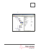
53SU6000 INSTALLATION AND SETUP GUIDE 4.0 START-UP AND OPERATION 4.1 53SU6000 Startup When 53SU6000 setup is complete, the Windows Program Group illustrated in Figure 4-1 is created. Figure 4-1. Micro-DCI Communications Services Program Group The function of the icons contained in the Micro-DCI Communications Services Program Group are detailed below: Documents Instruction Bulletins for Micro-DCI Communications Services and Micro-DCI controllers.
53SU6000 INSTALLATION AND SETUP GUIDE OPC Client The OPC Client makes data in OPC servers available to PC-FTRAN. OPC Test Client A simple OPC client, useful for testing OPC connectivity. 4.2 NAMING CONVENTIONS TAG.ATOM Notation Many applications use the TAG.ATOM naming convention to reference data values. The TAG portion of the name uniquely identifies the module containing the value. The ATOM portion uniquely identifies which of the values in the module is to be referenced. 4.2.1 TAGs 4.2.1.
53SU6000 INSTALLATION AND SETUP GUIDE 4.2.3 ATOMS 4.2.3.1 Types of ATOMnames There are two types of ATOMnames: SYMBOLIC ATOMNAMES Symbolic ATOMnames are short abbreviations for the name of the value, i.e. PV for Process Variable, etc. For 53MC5000’s and 53SL6000’s, consult the instruments’ Instruction Bulletins for the lists and descriptions of the various ATOMnames. Consult the online help in Super32.
53SU6000 INSTALLATION AND SETUP GUIDE 4.3 INTERFACING WITH THE Micro-PWC GLOBAL DBA The UdciGDS.ini file (located in the Windows root directory) allows several parameters of the Micro-PWC Global DBA system to be customized: [Events] AREA This parameter should be set to the area in which all Micro-DCI events will be reported. This value is ignored if an area as described in Section 4.0 is assigned. Values range from 1 to 255.
53SU6000 INSTALLATION AND SETUP GUIDE 4.4 ASSIGNING AREA, PRIORITY AND LEGENDS The Micro-PWC product and OPC Server expect that tagged modules contain several parameters which are not defined in Micro-DCI instruments. These parameters may be configured using the Configure Auxiliary Atoms dialog which may be called up from the tag context menu. These parameters are: LEGEND A legend of up to 32 characters can be configured to describe this tag in more detail.
53SU6000 INSTALLATION AND SETUP GUIDE 4.5 USING THE DDE SERVER The 53SU6000 includes a DDE server, udcidde.exe, for use in exporting the real-time data from the MicroDCI instruments to a third party DDE client such as Microsoft Excel. APPLICATION NAME udcidde.exe AVAILABLE TOPICS All module tag names displayed in the Super32 tree view. AVAILABLE ITEMS The Micro-DCI Global Database atoms.
53SU6000 INSTALLATION AND SETUP GUIDE 5.0 TROUBLESHOOTING 5.1 General Recommendations The 53SU6000 is primarily a software product which is installed in the user’s Personal Computer. This means the environment in which the 53SU6000 components are installed can be very site-specific. Table 5-1 provides general information and cross references to aid in problem resolution for problems arising during installation and setup of 53SU6000 components.
53SU6000 INSTALLATION AND SETUP GUIDE 30 Introduction
53SU6000 INSTALLATION AND SETUP GUIDE 6.0 SUPPORT SERVICES A number of support services are available to users of the 53SU6000 and other Micro-DCI software and equipment. These include training programs, software maintenance agreements, and replacement parts. 6.1 Software Maintenance Agreement A Software Maintenance Agreement provides the user with Software Update Service. Software Updates may provide modifications, improvements and/or enhancements to existing functionality.
53SU6000 INSTALLATION AND SETUP GUIDE Table 6-1. Interconnection Terminal Boards (ITB) MODEL PART NUMBER Datalink Card 172S001U02 Microlink Card 686B627U01 Communications 686B622U01 Table 6-2. Supervisor Cards MODEL PART NUMBER Datalink Card 686B574U02 Datalink Card w/PLC Option 686B574U03 Microlink Card 686B619U03 Microlink Card w/PLC Option 686B619U04 Redundant Microlink Interface 686B626U01 Table 6-3.
53SU6000 INSTALLATION AND SETUP GUIDE Table 6-4. Cable Assemblies Cable Function Datalink Card to Micro-DCI Instrument (screw terminals non-cord set) Datalink Card to 53MC1000 or 50KM2000 (cord-set receptacle units) [connector on both ends of cable] One per instrument required Microlink Card to 53MC5000 Datalink Card to CCI / CCO ITB Microlink Card to CCI / CCO ITB Length Feet. (Meters) Part Number 5 (1.5) 677B907U01 10 (3) 677B907U02 15 (4.6) 677B907U03 20 (6.1) 677B907U04 25 (7.
53SU6000 INSTALLATION AND SETUP GUIDE When ordering standard parts for the 53SU6000, use the part numbers and descriptions shown in Table 6-1 through Table 6-4. Order replacement parts from a factory sales office. Provide the part description, spare part order number and quantity. 6.4 Technical Documentation Additional copies of this manual can be obtained from the nearest factory sales office at a reasonable charge.
The Company’s policy is one of continuous product improvement and the right is reserved to modify the information contained herein without notice, or to make engineering refinements that may not be reflected in this bulletin. Micromod Automation assumes no responsibility for errors that may appear in this manual. © 2005 MicroMod Automation, Inc. MicroMod Automation, Inc. 75 Town Centre Drive Rochester, NY USA 14623 Tel. 585-321-9200 Fax 585-321-9291 www.micromodautomation.