
Users Guide User Manual


IB-23C003
TROUBLESHOOTING THE MINI LINK
4.3 FROZEN DISPLAY/NO RESPONSE FROM PC KEYBOARD
This type of problem is usually indicative of address or interrupt conflict on the personal
computer I/O channel. You must establish a clear range of eight bytes I/O address space
(in the range 000
h
to 3FF
h
) to successfully operate the Mini Link. In addition, there can be
no other installed devices using the same interrupt request line as the Mini Link.
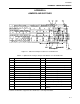
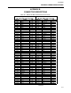
Use Table 2-1 as a guide to determine unused address space on your system's I/O
channel and Interrupt Request Bus. If you cannot determine the base addresses of the
installed hardware, contact the technical support representative of the hardware in
question.
If you continue to have difficulties in making the Mini Link work, contact your sales
representative.
4.3 NO RESPONSE FROM THE FIELD INSTRUMENTS
If communication has been established between the Mini Link and the Personal Computer,
but the instruments on the ICN do not respond, compare your configuration to the
checklist below:
1. The ICN (+) lead of the two-wire interface is connected to the terminal block (+)
screw on the rear of the Mini Link.
2. The ICN (–) lead of the two-wire interface is connected to the terminal block (–) screw
on the rear of the Mini Link.
3. If using the Isolation Feature (see jumper setting for W23), there is a third wire
connected between the Mini Link terminal block GND screw and ICN ground on the
instrument termination panel.
4. The length of the ICN (including the total length of the physical two-wire bus between
each node on the ICN and the length of the instrument cables between the nodes and
the instruments) does not exceed 2000 feet or 609.6m.
5. The ICN is appropriately terminated as described in the instructions for MOD 30 or
MODCELL.
6. If using a base configuration of the Mini Link (supporting 1 ICN) the two- wire interface
is connected to the Mini Link terminal block labeled ICN0.
7. If using a fully-configured Mini Link (supporting 2 ICNs) the two-wire interface for the
first ICN is connected to the Mini Link terminal block labeled ICN0 while the two-wire
interface for the second ICN is connected to the Mini Link terminal block labeled ICN1.
8. Instrument address is properly configured in hardware and software.
9. Mini Link ICN device address (as set by BCD switch SW1) does not conflict with any
instrument ICN device address.
4-2