
Instruction Manual

Logic Functions - Book 1
DIGITAL INPUT MODULE BLOCK (DIM)
5-6
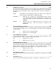
5.2.2 Digital Input Module Block Parameters
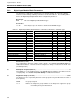
The mnemonics, valid values, and data types for all fields that may be selected for display
and/or be used in making softwiring connections are listed in Table 5-1. The following further
defines the Digital Input/Output Module Block configuration parameters.
Block Type
DIM This is the Digital Input Module Block type.
Occurrence
1 to 32 There may be up to 32 ‘instances’ allowed of the DIM block type.
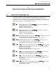
Table 5-1. Digital Input Module Block Attributes, Valid Values, Mnemonics, and Data Types
Field Name /
Attribute
Mnemonic Valid Values CWR Data Type Attr
Version VERSION – – R Long State 00
Block Length BLKLEN – – R Count 01
Block State STATE RUN (0) – – R Short State 02
Bad Inputs Accepted
BADINP YES (1) – – R Discrete 03
Diagnostic Group
SUPPGRP NONE, 1 to 7 CWR Long State 04
I/O Mismatch
MODMMS ENABLE (0), SUPPRESS (1) CWR Discrete 05
Unacked I/O Mismatch
MODMMU NO (0), YES (1) – WR Discrete 06
Active I/O Mismatch
MODMMA NO (0), YES (1) – – R Discrete 07
I/O Module Mismatch MODMM 0, 1 – – R Discrete 08
Board number BOARD 1 – – R Long State 09
Slot number SLOT 1 through 32 – – R Long State 10
Mode
MODE MANUAL (0), AUTO (1) CWR Discrete 11
Field Result
FR FALSE (0), TRUE (1) – – R Discrete 12
Field Result Quality
FRQ GOOD (0) or BAD (1) – – R Discrete 13
Initial Result Value
(Result)
R FALSE (0), TRUE (1) CWR Discrete 14
Result Quality
RQ GOOD (0) or BAD (1) – WR Discrete 15
02
Block State
(STATE).......................................................................................................... – – R
Not configurable in this block (always equal to RUN). See Section 2.4.1, Block States for
additional information. This block, when configured, is always executed in the RUN state
(Normal Operation).
03
Bad Inputs Accepted
(BADINP) ....................................................................................... – – R
This attribute is not used with this block. The DIM Module block always runs without a check
on input quality. See Section 2.3.2, Data Quality for additional information.
04
Diagnostic Group
(SUPPGRP)......................................................................................... CWR
The diagnostic errors reported by this block can be grouped for System Event block control of
their reporting.
NONE No group assigned.
1 to 7 Defines the diagnostic group number for the diagnostic suppression group
controlled by the System Event block.