
Instruction Manual

Logic Functions - Book 1
DIGITAL OUTPUT MODULE BLOCKS (DOM, DDOM, WDOM)
5-9
5.3 DIGITAL OUTPUT MODULE BLOCKS (DOM, DDOM, WDOM)
Digital output module blocks serve as the data handling blocks for the digital output modules.
The output module blocks have their data processed through an on-board select circuit that
passes all digital data between the module blocks and the modules at the base scan rate of 50
milliseconds. The digital output module block receives a read back value from the select
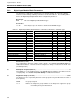
circuit for the module it is connected to. The valid output module types are:
DOM 2005A Solid State Relay Output
2007A Unconditioned Digital Output
DDOM 2011A Mechanical Relay Output (Dual SPST relay)
WDOM 2011A Mechanical Relay Output (Single Form C relay)
The digital output module blocks are data repositories for the instrument. All outputs are
buffered in one of five possible task state tables. Process input and output routines use these
tables to pass data between the module blocks which run at the base scan rate (50 msec) and
the process algorithm blocks which run at the configured scan group interval. All valid output
data for a single instrument (up to 32 digital output modules) is written by the output module
blocks every base scan cycle.
Digital output blocks can generate diagnostic errors based upon the following possible
conditions:
• I/0 mismatch
• Digital output module error
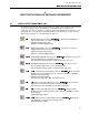
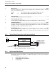
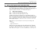
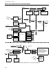
Available to the user as block outputs are the result, read back, track status, quality for the
same, and active and unacknowledged status of the block’s diagnostic errors. A functional
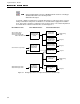
block diagram of a digital output module block is shown in Figure 5-5. This diagram is for the
DOM or WDO block and is typical of one channel of the DDOM block as shown in Figure 5-6.