
Instruction Manual

Logic Functions - Book 1
DIGITAL OUTPUT MODULE BLOCKS (DOM, DDOM, WDOM)
5-14
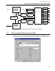
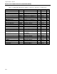
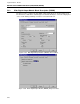
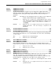
Figure 5-9. Digital Output Module (DOM), Diagnostic Menu
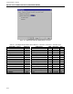
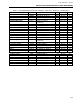
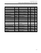
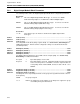
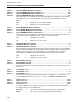
Table 5-3. Dual Digital Output Module Block Attributes, Valid Values, Mnemonics, and Data Types
Field Name /
Attribute
Mnemonic Valid Values CWR Data Type Attr
Version VERSION 1 – – R Long State 00
Block Length BLKLEN – – R Count 01
State
STATE RUN (0) – – R Short State 02
Bad Inputs
BADINP1 Rejected (0), Accepted (1) CWR Discrete 03
Diagnostic Group
SUPPGRP NONE, 1 to 7 CWR Long State 04
I/O Mismatch
MODMMS ENABLE (0), SUPPRESS (1) CWR Discrete 05
Unacked I/O Mismatch
MODMMU NO (0), YES (1) – WR Discrete 06
Active I/O Mismatch
MODMMA NO (0), YES (1) – – R Discrete 07
DDOM1 module error
DDOERRS1 ENABLE (0), SUPPRESS (1) CWR Discrete 08
Unacked DO Module Error DDOERRU1 NO (0), YES (1) – WR Discrete 09
Active DO Module Error
DDOERRA1 NO (0), YES (1) – – R Discrete 10
DDOM2 module error
DDOERRS2 ENABLE (0), SUPPRESS (1) CWR Discrete 11
Unacked DO Module Error DDOERRU2 NO (0), YES (1) – WR Discrete 12
Active DO Module Error
DDOERRA2 NO (0), YES (1) – – R Discrete 13
I/O Module Mismatch MODMM FALSE (0), TRUE (1) – – R Discrete 14
Board Number
BOARD 1 – – R Long State 15
Slot Number
SLOT 1 to 32 – – R Long State 16