
Instruction Manual

Logic Functions - Book 1
DIGITAL OUTPUT MODULE BLOCKS (DOM, DDOM, WDOM)
5-21
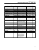
DOM 15
Mode
(MODE).....................................................................................................................CWR
DDOM 18
Mode
(MODE1)...................................................................................................................CWR
DDOM 28
Mode
(MODE2)...................................................................................................................CWR
WDOM 15
Mode
(MODE).....................................................................................................................CWR
The mode of the block is determined by configuring and/or writing this attribute. Switching
mode is a reportable event.
MAN 0 The block output is the result value, which may be written by the user.
The readback value is updated with the module value.
AUTO 1 The block output is processed using the input data.
DOM 16
Output to use on restart
(RESTART) ...............................................................................CWR
DDOM 19
Output to use on restart
(RESTART1) .............................................................................CWR
DDOM 29
Output to use on restart
(RESTART2) .............................................................................CWR
WDOM 16
Output to use on restart
(RESTART) ...............................................................................CWR
If a cold or frozen start up is occurring, the result will be set depending upon the selection
made here. If this block looses communication with the select circuit, a failsafe condition
results.
PREVIOUS 0 The result existing in the database prior to a failsafe output condition.
PRESET 1 A set value for failsafe output conditions (see preset output value).
DOM 17
Preset Output Value
(PRESET) ........................................................................................CWR
DDOM 20
Preset Output Value
(PRESET1) ......................................................................................CWR
DDOM 30
Preset Output Value
(PRESET2) ......................................................................................CWR
WDOM 17
Preset Output Value
(PRESET) ........................................................................................CWR
This is configurable discrete value when preset is selected as the output to use on restart.
FALSE 0 Preset output value is low.
TRUE 1 Preset output value is high.
DOM 18
Failsafe Output Value
(FSOUT) ........................................................................................CWR
DDOM 21
Failsafe Output Value
(FSOUT1) ......................................................................................CWR
DDOM 31
Failsafe Output Value
(FSOUT2) ......................................................................................CWR
WDOM 18
Failsafe Output Value
(FSOUT) ........................................................................................CWR
The failsafe output values are stored in the select circuit and are used to determine the output
sent to the module when a failsafe condition occurs. A write to the failsafe output value
causes the value to be downloaded to the module.
FALSE 0 Failsafe output value is low.
TRUE 1 Failsafe output value is high.
FS HOLD 2 Failsafe output value is last result value.
DOM 19
Track Status
(TRKSTAT) .................................................................................................. – WR
DDOM 22
Track Status
(TRKSTAT1) ................................................................................................ – WR
DDOM 32
Track Status
(TRKSTAT2) ................................................................................................ – WR
WDOM 19
Track Status
(TRKSTAT) .................................................................................................. – WR
Track status is set to track whenever the path from the input to the result is broken. This
occurs when the data quality is bad, or the I/O lock is locked, or when the mode is manual or
the instrument state is not run.
NO TRACK 0 Data quality is good, I/O lock is unlocked, mode is auto and
instrument state is run.
TRACK 1 Data quality is bad, or I/O lock is locked or mode is manual, or
instrument state is not run.