
Instruction Manual

Logic Functions - Book 1
DIGITAL OUTPUT MODULE BLOCKS (DOM, DDOM, WDOM)
5-23
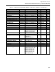
DOM 26
Result
(R)............................................................................................................................– – R
DDOM 40
Result
(R1)..........................................................................................................................– – R
DDOM 44
Result
(R2)..........................................................................................................................– – R
WDOM 26
Result
(R)............................................................................................................................– – R
This is the result of the block evaluation after action is applied.
FALSE 0 Result sent to output module (after action is applied) is open.
TRUE 1 Result sent to output module (after action is applied) is closed.
DOM 27
Result Quality
(RQ)........................................................................................................... – WR
DDOM 41
Result Quality
(RQ1)......................................................................................................... – WR
DDOM 45
Result Quality
(RQ2)......................................................................................................... – WR
WDOM 27
Result Quality
(RQ)........................................................................................................... – WR
The result quality is set BAD when the input status is bad and bad inputs are not accepted, or
if the restart or readback value cannot be read after a warm start. Any write to the result
causes the result quality to be set GOOD. The result quality is writeable in manual, when the
I/O is locked, or the instrument state is not run.
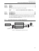
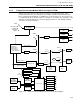
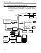
5.3.5 Typical Block Connections for Digital Output Blocks
Typical softwiring block structures used on softwiring diagrams are shown in Figure 5-11.
Slot 8
Operator write access to set mode and action.
MODE
R
DO1
Operator indication of
result and block mode.
Input
Mode
1
2
Result
Action
HILIM
TM1
High Limit
Figure 5-11. Digital Output Block, Typical Connections