
Instruction Manual

Logic Functions - Book 1
DIGITAL INPUT BLOCK
7-31
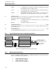
Input Module ......................................................................................................................C – –
DIM1 A Digital Input Module (DIM) is the only valid input module type as
connected through MODIN. Occurrence numbers may be from 1 to
32.
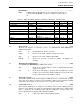
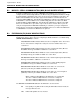
Table 7-7. Digital Input Block Attributes, Valid Values, Mnemonics, and Data Types
Field Name /
Attribute
Mnemonic Valid Values CWR Data Type Attr
Version VERSION 1 – – R Long State 00
Block Length BLKLEN – – R Count 01
Block State
STATE RUN(0), HOLD(1), OFF(2),
DEBUG(3)
CWR Short State 02
Bad Inputs Accepted
BADINP NO (0), YES (1) CWR Discrete 03
Filter type FILTYPE NONE (for future use) CWR Short State 04
Filter Time
FILTIME 0 to 65500 (milliseconds) CWR Count 05
Latch Value
LATCH ANY(0), FALSE(1), TRUE(2),
TRANS.(3)
CWR Short State 06
Action
ACTION REVERSE (0), DIRECT (1) CWR Discrete 07
Initial Result Value
R FALSE (0), TRUE (1) CWR Discrete 08
Result Quality
RQ GOOD (0), BAD (1) – WR Discrete 09
02
State
(STATE).....................................................................................................................CWR
All block state changes are reported as events. See Section 2.4.1, State Changes for
additional information.
RUN 0 Normal Operation. Block is executed.
HOLD 1 Block is not executed. Qualities retain previous values.
OFF 2 Block is not executed. Qualities will be BAD.
DEBUG 3 Block is not executed. No fields are updated. All attributes are
writeable.
03
Bad Inputs Accepted
(BADINP)........................................................................................CWR
See Section 2.3.2, Data Quality for additional information.
YES 1 Block runs its algorithm without a check on input quality and output
quality is set to good.
NO 0 Block checks data quality on its inputs and only updates the result if
its input is good. If the input quality is BAD, the result is held at the
previous value and the result quality is set bad.
05
Filter Time
(FILTIME) .........................................................................................................CWR
The filter time attribute allows an input signal to stabilize before it is considered valid. An input
value state must remain consistent for the total number of milliseconds specified (0 to 65500
rounded up to the next base scan cycle) before it is accepted as an input value.
06
Latch Value
(LATCH) .........................................................................................................CWR
Since physical digital inputs are sampled at a 50 millisecond rate and the digital input block
may be in a loop running at a slower rate, input latching may be applied to the sampled input
value to ‘synchronize’ the conditioning values with the conditioning. The latch value of the
block is determined by configuring and/or writing this attribute.
ANY 0 If ANY is specified, no input latching is applied.