Totalization for MOD 30ML and Modcell Application Guide
MicroMod Automation, Inc. The Company MicroMod Automation is dedicated to improving customer efficiency by providing the most cost-effective, application-specific process solutions available. We are a highly responsive, application-focused company with years of expertise in control systems design and implementation. We are committed to teamwork, high quality manufacturing, advanced technology and unrivaled service and support.
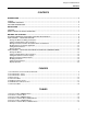
Using The Totalizer Block Contents CONTENTS INTRODUCTION ................................................................................................................................................. 2 SCOPE ............................................................................................................................................................... 2 FIRMWARE VERSIONS ........................................................................................................................
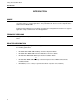
Using The Totalizer Block Introduction INTRODUCTION SCOPE This book is one of a series that discusses the application of MOD 30ML™ to commonly encountered process control applications. This particular book discusses how to implement the totalizer block in MOD 30ML. Included in this publication is a functional description and configuration instructions for a typical application using a totalizer block in a PID application.
Using The Totalizer Block Description DESCRIPTION GENERAL Many flow applications require simultaneous control and totalization of the process. In the past a separate device was commonly used for totalization while flow control was left to a PID controller. If there was to be any interaction or relationship between the two devices it was often difficult if not impossible to implement. MOD 30ML can provide accurate PID control and totalization for multiple loops.
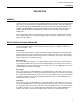
Using The Totalizer Block Description Figure 1. Totalizer Basic Functional Block Diagram Run Input This is a discrete input command which if used would normally be sourced from a LSP such as a momentary digital input like a remotely mounted push button. The Run action takes place when the Run input transitions from false to true. This causes the totalizer mode to be set to Run from a Hold or Stop mode.
Using The Totalizer Block Description used to increment a counter identifying how many times the totalizer has wrapped. The High Limit Status line will reset to false on the next block execution if Auto Wrap is set to yes. Threshold Typically set at time of configuration. This is the value in engineering units by which the Analog Input (totalizer input) must exceed before the totalizer will count. The purpose of this feature is to ignore the counting of unwanted process or transmitter drift.
Using The Totalizer Block Description High Limit Typically set at time of configuration. This is the value at which a totalizer counting up will stop counting at. If the up counting totalizer is set to Wrap, then this is the value that will cause the wrap to happen. It is also the value at which a totalizer counting down will reset to in the event of a Reset command. Low Limit Typically set at time of configuration. This is the value at which a totalizer counting down will stop counting at.
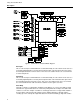
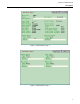
Using The Totalizer Block Description Figure 2. Totalizer Block, Page 1 Figure 3.
Using The Totalizer Block Description 8
Using The Totalizer Block Building the Strategy BUILDING THE STRATEGY BUILDING A WORKING TOTALIZER STRATEGY WITH DISPLAY You must be inside a loop compound to build this strategy. It is assumed that the user of this document has a basic understanding of Application Builder software. The totalizer and PID parts of the strategy are relatively straight forward. We will offer two different display options in this application document.
Using The Totalizer Block Building the Strategy Making connections between the totalizer block and PID block. 1. Select the connection tool. 2. Select the PID block. A sub-menu will appear. 3. Press “NEXT” twice. 4. Select the PVI attribute from this menu. 5. Select the Totalizer block. A new sub-menu will appear. 6. Select ANALINP attribute from this menu. The totalizer now has an input for totalizing. 7. Select the CMD attribute from the Totalizer block. 8. Connect it to I10 of the Display block.
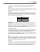
Using The Totalizer Block Building the Strategy Table 2. Edit Display Format Date Format Name Display Format Low Limit High limit Entry Method TotalL ActionL Float0 State 0 1000000.0 None Ent. Req. Display State Table Entry State Table ActionD ActionE 11. Click on the red diamond in the upper left corner of the Edit Display Formats menu to close it. 12. Select . 13. Modify the existing Display block script to appear as that in Figure 3.
Using The Totalizer Block Building the Strategy } /* so as not to cause continuos sends */ /* of the ACTION value. */ IF DELTA THEN /* The CMD register will always be zero */ { ACTION = 0; /* display totalizer value when ACTION */ DELTA = 0; /* command is entered to confirm entry */ #LINE5 = "TOT"; #LINE6.SRC = TOTAL; #UPDN = 1; } } } Figure 3. Display Script 14. Save and exit from the display scripts. 15. Click on to close the Display block. 16.
Using The Totalizer Block Building the Strategy Adding Communications 1. Select the Library icon. 2. Select Communications from the library menu. 3. On the left side of the screen select the communications block required for the protocol being used. Select either a Modbus or ICN block. 4. Place the block near the loop compound. 5. Open the block and set the slot location.
Using The Totalizer Block Building the Strategy APPLICATION 2 - TOTALIZER AND PID WITH SEPARATE COMMANDS MENU Application 2 will include the totalized value as part of the PID display. However, the totalizer commands menu is assigned to a separate display tag. You must be inside a loop compound to build this strategy. Placing The Blocks As a shortcut we will be loading a direct connect PID loop compound from the compounds library.
Using The Totalizer Block Building the Strategy Adding the totalizer commands display. 1. Select the Library icon from the top of the screen again. 2. Select SYSTEM. 3. On the left side of the screen, from the system menu select and drag to the work area a block. Place it above the Display block. 4. Enter the block. 5. In the Block Tag field enter “TOTDISP”. 6. Close the block by clicking on . Making connections between blocks. 1. Select the connection tool. 2. Select the PID block.
Using The Totalizer Block Building the Strategy Table 3. Edit Inputs Data, PIDDISP Block Input No. I10 1 Input Name Type TOTAL Remote1 Line Format TOTALL Changes to Remote automatically happen when an external connection is made. 7. Close the Inputs menu by clicking on the red diamond in the upper left corner of the block. . 8. Select 9. Enter the information from Table 4 into field format F8. Table4.
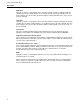
Using The Totalizer Block Building the Strategy BREAK; 2: #LINE5 = "TOT"; #LINE6.SRC = TOTAL; BREAK; } } SCROLL_HELD: { TUNE; } } Figure 5. PID Display Block Script 13. Exit and save the Display block scripts. 14. Click on to close the PIDDISP Display block. 15. Enter the TOTDISP Display block. 16. In the Display Tag field enter the loop tag name of your choice for the totalizer commands display.
Using The Totalizer Block Building the Strategy Table6. Edit Display Format Date, TOTDISP Block Format Name Display Format Low Limit High limit Entry Method Display Entry State State Table Table TOTALL ACTIONL Float0 State 0 1000000.0 None Entry Req’d ACTIOND ACTIOND 26. Close the Display Formats menu by clicking on the red diamond in the upper left corner of the block. . 27. Select 28. Add Display block script to appear as that found in Figure 6.
Using The Totalizer Block Building the Strategy 39. At the bottom of the state table list add the following table. ACTIOND, 8, "????????" { 0, "NONE"; 1, "RESET"; 2, "STOP"; 3, "RUN"; 4, "HOLD"; } Figure 7. State Table Data 40. Exit and save the state table list. 41. Close the State Table block by selecting . Adding Communications 1. Select the Library icon. 2. From the library menu select Communications. 3.
Using The Totalizer Block Building the Strategy Display Operation Unless other changes were made in the strategy to cause a different behavior, the instrument will come up in a manual mode with a local set-point. The output is displayed on the bottom line. Pressing the scroll key once causes the set-point to be displayed on the bottom line. Pressing the scroll key a second time causes the totalized value to be displayed on the bottom line.
The Company’s policy is one of continuous product improvement and the right is reserved to modify the information contained herein without notice, or to make engineering refinements that may not be reflected in this bulletin. Micromod Automation assumes no responsibility for errors that may appear in this manual. © 2004 MicroMod Automation, Inc. Printed in USA IB-MLAPP-TOT, Issue 2 MicroMod Automation, Inc. 75 Town Centre Drive Rochester, NY USA 14623 Tel. 585-321 9200 Fax 585-321 9291 www.