MODCELL™ Multiloop Processor and MOD 30ML™ Multiloop Controller Diagnostic Information and Troubleshooting Procedures for 2001N, 2002N, and 1800R Maintenance
MicroMod Automation, Inc. The Company MicroMod Automation is dedicated to improving customer efficiency by providing the most cost-effective, application-specific process solutions available. We are a highly responsive, application-focused company with years of expertise in control systems design and implementation. We are committed to teamwork, high quality manufacturing, advanced technology and unrivaled service and support.
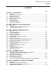
MOD30ML and Modcell Maintenance CONTENTS CONTENTS Page SECTION 1 - INTRODUCTION 1.1 1.2 1.3 1.3.1 1.3.2 1.3.2 1.3.3 1.4 1.5 GENERAL ..............................................................................................................................1-1 INSTALLATION INTEGRITY ..................................................................................................1-1 DIAGNOSTIC TOOLS .........................................................................................................
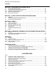
MOD30ML and Modcell Maintenance CONTENTS SECTION 6 - DIAGNOSING SHUTDOWN FAULTS 6.1 6.2 6.2.1 6.2.2 6.2.3 SHUTDOWN INFORMATION ............................................................................................... 6-1 RECORDING SHUTDOWN INFORMATION ........................................................................ 6-1 Application Builder/ViZapp Method ....................................................................................... 6-2 MOD 30ML Display Method .........................
MOD30ML and Modcell Maintenance CONTENTS 3-9 3-10 3-11 3-12 3-13 3-14 3-15 3-16 3-17 3-18 3-19 3-20 3-21 3-22 3-23 3-24 3-25 4-1 5-1 6-1 6-2 8-1 8-2 8-3 8-3a 8-4 8-4a MicroMod Extended Modbus OPC Server database..............................................................3-11 MicroMod ICN OPC Server.....................................................................................................3-12 Add new ICN Device ....................................................................................
MOD30ML and Modcell Maintenance CONTENTS Notes 1 -4
MOD30ML and Modcell Maintenance INTRODUCTION SECTION 1 INTRODUCTION 1.1 GENERAL The MODCELL and MOD 30ML instruments contain extensive internal diagnostics, which continuously monitor instrument operation. If a malfunction is detected it is immediately reported so that the user can take appropriate action. In addition, most routine instrument events such as changes in operating state, switching of control modes, suppression or enabling of various diagnostics, acknowledgement of alarm conditions, etc.
MOD30ML and Modcell Maintenance INTRODUCTION 1.3 DIAGNOSTIC TOOLS The MODCELL and MOD 30ML instruments are supported by the following diagnostic tools: • MODCELL Status LEDs • Application Builder Software • MOD 30ML Display • Mini Link / External Status LEDs Use of these tools can provide diagnostic information which helps identify most instrument problems. 1.3.
MOD30ML and Modcell Maintenance INTRODUCTION 1.4 REPAIR PHILOSOPHY The repair philosophy for the MODCELL and MOD 30ML instruments is repair by replacement at the module level. The module level includes those instrument components, which can be removed and installed manually via plug-in connections. The modularized design of these instruments permits easy field replacement of components such as I/O modules, communication modules, identity module and the portable memory module.
MOD30ML and Modcell Maintenance INTRODUCTION 1 -4 • IB-1800R-SCR – Display Guide – Scripting hints, help and examples formed 30ML using ViZapp Software • IB-MLOPR-TUT – MOD 30ML Operation Training manual
MOD30ML and Modcell Maintenance MODCELL STATUS INDICATORS SECTION 2 MODCELL STATUS INDICATORS 2 .1 GENERAL The red and green status LEDs on each MODCELL instrument, Figure 1 or 2, provide continuous visual indication of the operational condition of the instrument.
MOD30ML and Modcell Maintenance MODCELL STATUS INDICATORS • Memory module and database checks If a memory module is present and its switch is in the MODULE LOAD position, the instrument enters and runs in the UPLOAD state. During upload, the red LED is on. If a valid main database is present and is successfully copied to the backup memory module, the red and green LEDs will remain on.
MOD30ML and Modcell Maintenance MODCELL STATUS INDICATORS Figure 2-1. Component Location, 2001N Processor Figure 2-2.
MOD30ML and Modcell Maintenance MODCELL STATUS INDICATORS Table 2 -1. Status LED Troubleshooting Guide Status LED Condition Red off Green off Problem No power Probable Cause 1. Power not turned on. 1. Turn on power. 2. Power not connected at distribution panel (AC source). 2. Connect power. 3. Instrument power supply failed.
MOD30ML and Modcell Maintenance MODCELL STATUS INDICATORS Status LED Condition Red on Green on (Cont’d) Problem After power-up instrument is in UPLOAD state Instrument operating normally in RUN state, changes to HOLD state. Instrument in HOLD state. All checking is complete and Instrument is in LOCAL HOLD State Red flashing green on After power-up, memory module upload failure. Probable Cause Memory module switch is set at LOAD; main database has been successfully copied to memory module.
MOD30ML and Modcell Maintenance MODCELL STATUS INDICATORS Notes: 2 -6
MOD30ML and Modcell Maintenance VIEWING DIAGNOSTIC DATA SECTION 3 VIEWING DIAGNOSTIC DATA 3.1 GENERAL The purpose of this section is to provide specific how-to instructions for viewing diagnostic data and issuing commands to the instrument. Three methods are available: 3.2 • Application Builder Software The 2006S Application Builder Software can be used to view diagnostic event data and issue commands to MODCELL and MOD 30ML instruments. See Section 3.2.
MOD30ML and Modcell Maintenance VIEWING DIAGNOSTIC DATA 3.2.1 Starting the Application Builder This procedure is based on the assumption that the software is installed as described in IB23H141. Start the program using the step-by-step instructions in the next. Table 3 .1. Application Builder Startup Procedure . Step Procedure Comments 1 Access the DOS prompt for the drive and directory where the Application Builder resides.
MOD30ML and Modcell Maintenance VIEWING DIAGNOSTIC DATA Figure 3.1. Application Builder Untitled - [Root] Display Figure 3.2.
MOD30ML and Modcell Maintenance VIEWING DIAGNOSTIC DATA Step 7 8 9 10 11 Procedure Comments Configure the selected port as follows: • If your software is Version 3.00 or lower, select the Link Type Field and scroll to obtain Link for ICN communication or None for Modbus Communication. This field is not used in later versions. • If necessary, select the base address field and enter the required address. • Select the Baud Rate, Data Bits, Parity, and Stop Bits fields.
MOD30ML and Modcell Maintenance VIEWING DIAGNOSTIC DATA 3.2.2 Setting Up Communications This procedure provides for the selection of the specific instrument on which diagnostic data is required, and defines the required communication parameters. Perform the setup procedure using the step-by-step instructions in the next Table. Table 3 .3. Communication Setup Procedure Step Procedure 1 On the Instrument Status display, Figure 3.3 or 3.4, click on Setup. The communication setup menu, Figure 3.
MOD30ML and Modcell Maintenance VIEWING DIAGNOSTIC DATA Figure 3.3. Instrument Status Display, Version 4.0 and Lower Versions Figure 3.4. Instrument Status Display Version 4.
MOD30ML and Modcell Maintenance VIEWING DIAGNOSTIC DATA Figure 3.5. Communications Setup Menu Step Procedure 6 Leave the Log File entry at No; scrolling to Yes will slow communication activities. 7 Select the Database to Read field and if necessary, scroll to select Current Ignore the fields related to downloading. They do not apply to diagnostics. Select OK to activate the setup entries and return to the Instrument Status display.
MOD30ML and Modcell Maintenance VIEWING DIAGNOSTIC DATA 3.3 VIZAPP SOFTWARE Diagnostic data is viewed via the Instrument Status display in the ViZApp Software. This display also supports the issuance of a series of instrument commands, and read/write commands to specific block attributes The following sections provide procedures for accessing the status page, setting up communications with the required instrument, and then executing commands as required.
MOD30ML and Modcell Maintenance VIEWING DIAGNOSTIC DATA The communication parameters for the built-in communication port of the MOD 30ML are setup from the front face of the controller using the SETUP menu. 3.3.4 Setting up Communications with XModbus OPC Server In the following example, we will use the built-in communication port of the MOD 30ML selected as RS-232 Modbus using the comm. port jumper on the main board. Table 3 .4.
MOD30ML and Modcell Maintenance VIEWING DIAGNOSTIC DATA Figure 3.7. Add new Extended Modbus Device 4 We will configure the properties of the device we are adding in this dialog box. • Type the name MOD30ML in the Name field (the name is user-configurable and can be anything!). • Select the serial communication port of the computer to which the MOD 30ML is connected, in the Port field. Click on the down arrow in this field to show the list of enabled serial ports and then select the port.
MOD30ML and Modcell Maintenance VIEWING DIAGNOSTIC DATA Figure 3.8. Port Properties 7 Choose the Baud Rate, Parity, Flow Control, Data bits and Stop bits from this dialog box. Click on OK to complete the Port configuration. Make sure these entries match the settings of the instrument. 8 Leave other fields on this dialog box at their default values. Click on OK. The Extended Modbus Device Properties dialog box will redisplay with the port number.
MOD30ML and Modcell Maintenance VIEWING DIAGNOSTIC DATA Figure 3.10. MicroMod Extended Modbus OPC Server database 10 11 11 3 -12 Save the database: Select File – Save from the menu bar. Refer to the following figure. Type a name for the OPC tag database file in the File name field. Click on the Save button to save the file. You can now either minimize the Extended Modbus OPC Server application or close it. The Save As dialog box will be displayed next.
MOD30ML and Modcell Maintenance VIEWING DIAGNOSTIC DATA 3.3.5 Setting up Communications with ICN OPC Server In the following example, we will use the built-in communication port of the MOD 30ML selected as ICN using the comm. port jumper on the main board. Table 3 .5. Setting up communications with ICN OPC Server Step Procedure 1 Launch the ICN OPC Server: From the Windows Start menu, select Programs-MicroMod Automation – Control Solutions Software Suite - ICN OPC Server.
MOD30ML and Modcell Maintenance VIEWING DIAGNOSTIC DATA computer to which the ICN Link (1731N or 1733N Mini link or 1720N Communication Link) MOD 30ML is connected, in the Port field. Click on the down arrow in this field to show the drop-down menu and then select the port. (COM1 for example). • Type the ICN number in the ICN Number field. This is the ICN card’s number in the 1720N Communication Link or 0 or 1 in the case of Mini-link or Mini-link Ext.
MOD30ML and Modcell Maintenance VIEWING DIAGNOSTIC DATA file and then select the file. Click on the Open button on this dialog box. shown). The selected .MIF file name will be displayed in the File Name field of the dialog box (see the next figure). Note: If you are not using the OPC Server or any other host software package for Human System Interface, you do not have to specify the .MIF file. Figure 3.13.
MOD30ML and Modcell Maintenance VIEWING DIAGNOSTIC DATA Click on OK to complete the Port configuration. Make sure these entries match the settings of the instrument. 10 Open the device by double-clicking on it and select the serial port from the Port drop-down list. The default values for baud rate, data bits and stop bits for various communication equipment are shown in Table 3.2. See the next figure. Figure 3.15.
MOD30ML and Modcell Maintenance VIEWING DIAGNOSTIC DATA Figure 3.16. Save ICN OPC Server File 12 13 14 Save the database: Select File – Save from the menu bar. Refer to the following figure. Type a name for the OPC tag database file in the File name field. Click on the Save button to save the file. The Save As dialog box will be displayed next. The Title bar of the OPC Server will redisplay with the saved file name. Note that the file has an extension .ICNS.
MOD30ML and Modcell Maintenance VIEWING DIAGNOSTIC DATA 3.3.6 Instrument Status Viewer Table 3 .6. Instructions for using Instrument Status Viewer Step Procedure 1 2 Switch back t the ViZapp Software. Start the Instrument Status Viewer: Select Instrument – Status from the menu bar at the top. This will display the Communication Setup dialog as shown below: Comments This will show the Server name and the Device name in the respective fields. Figure 3.17.
MOD30ML and Modcell Maintenance VIEWING DIAGNOSTIC DATA Figure 3.18. Select OPC Server Click on the Browse button near the Device Name field. Select the device you need to communicate to from the list The OPC Server will be launched. A menu will appear listing all the devices from the OPC Server file that was last opened by the OPC Server. Figure 3.19.
MOD30ML and Modcell Maintenance VIEWING DIAGNOSTIC DATA Figure 3.20. Communication Setup 3 4 3 -20 Make no changes to the other fields in this dialog box. Click on OK. This will start the Instrument Status display as shown below: This Instrument Status display has a text field to enter commands and a set of buttons.
MOD30ML and Modcell Maintenance VIEWING DIAGNOSTIC DATA Figure 3.21.
MOD30ML and Modcell Maintenance VIEWING DIAGNOSTIC DATA 3.3.7 Printing from the Status Window to a text file: Table 3 .7. Instructions for printing to a text file 1 2 3 3 -22 Add a printer in the Printers menu from the Windows Control Panel. Select Local Printer and then choose Text in the Select Printer Port menu Select Generic as the manufacturer and select Generic/Text only as the printer Type a name for the printer.
MOD30ML and Modcell Maintenance VIEWING DIAGNOSTIC DATA 3.4.1 Reading Diagnostics Commands are typed on the command line near the bottom of the status display (Figures 33, 3-4 and 3-17) and sent to the instrument by clicking on the ENTER button or pressing the enter key. The command for reading diagnostics is: R DIAGS type When typing this command, the letter R and the abbreviation DIAGS must be followed by a space.
MOD30ML and Modcell Maintenance VIEWING DIAGNOSTIC DATA • Event Code and Message Text - Each diagnostic in a block has a unique code number (8 in the example), and a brief text message (WRIM MODULE ERROR) is appended to the code to indicate the nature of the problem. Use the block type and event code to locate the diagnostic description and corrective action listed in Section 7.
MOD30ML and Modcell Maintenance VIEWING DIAGNOSTIC DATA o • ACK ONLY - Diagnostics resulting from a momentary occurrence where the abnormal condition is not sustained. This class is sometimes accompanied by a counter attribute, which counts the number of occurrences. Status - The diagnostic status at the time the read command is received (UAK G ACT G in the example).
MOD30ML and Modcell Maintenance VIEWING DIAGNOSTIC DATA messages, and use the block type and event code to find description/action information in Section 7.3 3.4.2 Reading and Writing Block Attributes The command format for reading or writing block attributes is as follows: Figure 3.24.
MOD30ML and Modcell Maintenance VIEWING DIAGNOSTIC DATA Table 3 .8.
MOD30ML and Modcell Maintenance VIEWING DIAGNOSTIC DATA 2004P MODCELL Batch Controller Version 1 GxA__1xxxxxxx 2004P MODCELL Advanced Controller Version 2 GxA__2xxxxxxx 2004P MODCELL Advanced Controller Version 3 GxA__3xxxxxxx –––––––––––––––––––––––––––––––––––––––––––––––––––––––––––––––– 1800P MOD 30ML Controller Functions Version 2 IxA__2xxxxxxx IxA__1xxxxxxx 1800P MOD 30ML Controller Functions Version 1 2.
MOD30ML and Modcell Maintenance VIEWING DIAGNOSTIC DATA 3.5 MOD 30ML DISPLAY The instrument display supports viewing of diagnostic data and implementation of several commands as described in the following sections. NOTE: If the Application Builder software is available for use with the MOD 30ML instrument, use of this software as described in Section 3.2 provides more comprehensive diagnostic data and offers a wider command selection than the instrument display. 3.5.
MOD30ML and Modcell Maintenance VIEWING DIAGNOSTIC DATA 3 Press down arrow to enter the event queue. Page 1 for the first event in the queue appears (figure at the bottom left of next page). 4. View the events in the queue as follows: • Press the down arrow again to view page 2 for the first event. • Press the up arrow to return to page 1. • Press NXT to view the next event; use down and up to view page 2 as required.
MOD30ML and Modcell Maintenance VIEWING DIAGNOSTIC DATA Figure 3.26. Device Status and Device Event Displays Page 1 Page 2 Figure 3.27.
MOD30ML and Modcell Maintenance VIEWING DIAGNOSTIC DATA 3.5.2 MOD 30ML Commands Access the commands as follows: 1. Press and hold the TAG key to obtain the Device Status display. 2. Press the down arrow to enter the status setup sequence. The Device State (DEV STAT) display or password request (CONFIG PASSWORD) display appears. 3. If a configuration password if required, proceed as follows: o Use the arrow keys to display the password number.
MOD30ML and Modcell Maintenance VIEWING DIAGNOSTIC DATA 3 -33
MOD30ML and Modcell Maintenance Manual COMMUNICATIONS SECTION 4 COMMUNICATIONS 4.1 COMMUNICATING WITH A REPLACEMENT INSTRUMENT ! CAUTION When replacing an instrument on an ICN or MODBUS network, serious network communication problems can occur if the assigned address of the new instrument matches the address of another device on the network. Be sure the address setting of the new instrument is correct before connecting it to the network.
MOD30ML and Modcell Maintenance Manual COMMUNICATIONS 4. Press the NXT key to access the Device Setup Display, then press the down ( ) key to enter the setup sequence. 5. Configure the built-in (BI) communication parameters as follows: • For ICN communication: 1. Set ICN address to match the address of the instrument being replaced. 2. Set ICN status active by entering YES in response to the ENABLE? prompt. • For Modbus communication: 1.
MOD30ML and Modcell Maintenance Manual COMMUNICATIONS • The link can contain as many as 8 ICN interface boards each connected to a single ICN with as many as 15 instruments. The interface board and instruments on each ICN must have unique addresses. The hexadecimal address switch on each interface board is factory set at 0; this allows addresses 1-15 ($1-$F) to be assigned to the instruments via the ICN module address switch. The interface board can be assigned any address (1-15).
MOD30ML and Modcell Maintenance Manual COMMUNICATIONS ICN connector is labeled with a ground symbol; disregard this marking because the terminal functions as the common connection. 6. Apply power to the equipment. If the network contains a Mini Link, allow at least 30 seconds for the link to initialize. 7. Verify that the ICN has proper termination. The most common termination method uses the 2030F ICN terminator connected to the terminal block of one instrument on the network.
MOD30ML and Modcell Maintenance Manual COMMUNICATIONS 10. Access the Instrument Status Display and click on the command line at the bottom of the screen. Type R VERSION and click on Enter. This command returns the version of any instrument connected to the ICN, even MOD 30. If the instrument responds, confirm that the reported version agrees with the type of instrument that is being tested. The version return data is listed in Section 3.4.3. 11.
MOD30ML and Modcell Maintenance Manual COMMUNICATIONS can be set to YES to provide the required resistors. 5. Apply power to the instrument. 6. Start the Application Builder software and access the Serial Port Setup menu, Figure 3.2. (see Section 3.2.1 for detailed procedure). Select the serial port that is connected to the instrument and confirm the port settings. The standard Base Addresses are 3F8, 2F8, 3E8 and 2E8 for Com1 through Com4 respectively.
MOD30ML and Modcell Maintenance Manual COMMUNICATIONS does not match the address of any instrument on the ICN. • Note the number of each ICN. The ICNs are numbered 0 through 7 from left to right. Earlier model links may number the ICNs 1 through 8 on the chassis, though this address scheme is not used in the Application Builder. The ICN number is not related to the ICN interface board address: they can have the same numerical value. • Note the link switch settings.
MOD30ML and Modcell Maintenance Manual COMMUNICATIONS ICN operation is to check the voltage pattern with an oscilloscope. The voltage traces for a properly functioning ICN are shown in Figure 10. 9. Access the Device Setup display on instrument front panel and verify the following: • The instrument being tested is set at a different ICN address than the address switch on the ICN interface board in the link. • ICN communication is enabled 10.
MOD30ML and Modcell Maintenance Manual COMMUNICATIONS 4. If RS-485 communication is being used, verify that the connection at the computer (Modbus Master) is made via an RS-485 interface card containing the required bus stabilizing resistors. NOTE: The Port Functionality attribute of the MSC block must be configured as a slave. 5. Apply power to the instrument. 6. Access the device setup display on the instrument front panel.
MOD30ML and Modcell Maintenance Manual COMMUNICATIONS 4.2.5 Mini Link/ External Front Panel Indicators LEDs) on the Mini Link / External indicate the health status of the ICNs. The front panel of the External Mini Link is divided into two sections labled ICN0 and ICN1. Each section has three LED indicators as described below: ENABLED: When lit, this LED indicates that the circuit controlling the instrument communications through the corresponding ICN is active and responding properly to the main processor.
MOD30ML and Modcell Maintenance Manual COMMUNICATIONS 4.3 APPLICATION BUILDER/ VIZAPP INSTRUMENT COMMUNICATION MESSAGES When using the Application Builder Software to communicate with a MODCELL or MOD 30ML instrument, the software provides numerous messages, which inform the user about the communication activity. The messages can appear during database downloading, uploading or importing activities, and during communication activity initiated through the instrument status display.
MOD30ML and Modcell Maintenance Manual COMMUNICATIONS Table 4 .1. Communication Messages, Cause and Recommended Action Message Probable Cause Attribute not write able Attribute is read only. Block creation failed 1. Unable to decompile instrument database (.ID1) file during upload from instrument to Application Builder. 2. Unable to decompile 1706S Configurator .ID1 file during import into Application Builder.
MOD30ML and Modcell Maintenance Manual COMMUNICATIONS Message Comm errors detected, Please exit debug mode Or Comm errors detected for document name, Debug mode not available. CRC error. Cross reference table creation failed Data comparison error Database file exists. Overwrite? Database not loaded Database not supported by this algorithm set Probable Cause This error occurs when entering ViZapp’s Debug mode and on or more of the instrument document (.
MOD30ML and Modcell Maintenance Manual COMMUNICATIONS Message Deferred response overrun, parity or framing error Probable Cause 1. Momentary communication fault. 2. Parity mismatch between instrument and Communications Link. Device: device name not found in Server. Do you wish to retain block occurrence numbers in the compound being loaded? Same cause as GetAddress message in this table This message appears whenever a compound is loaded.
MOD30ML and Modcell Maintenance Manual COMMUNICATIONS Message Error writing .ID1 or .ID2 file Error writing .SD1 file GetAddress: Unspecified Error Probable Cause Instrument data base file (.ID1) or LCP data base file (.ID2) cannot accept data because: 1. Disk is full. 2. Wrong drive selected. 3. Diskette not installed. Shutdown data file (.SD1) cannot accept data because disk is full. This error occurs while entering one of the following modes: Status, Upload or Download in ViZapp.
MOD30ML and Modcell Maintenance Manual COMMUNICATIONS Message Instrument is not a MODCELL or MOD 30ML Instrument reports an error reading that attribute Instrument state in transition Instrument version too low to run data base Interpreting database Invalid ACK Invalid ASCII string Invalid attribute Invalid block checksums Followed by: Possibly invalid database. Do you wish to continue? Invalid block type 4 -16 Probable Cause A MOD 30 instrument or LCP is connected at the specified ICN address. 1.
MOD30ML and Modcell Maintenance Manual COMMUNICATIONS Message Probable Cause Invalid block type or occurrence number An invalid block type or occurrence number was specified: e.g., ACK AI1 5 (AI is invalid block type for a Builtin Analog Input block; AIN is correct) e.g., ACK AIN9 5 (9 is an invalid occurrence number for a Built-in Analog Input block) A data constant entered in an expression is invalid: 1. Error occurs during a compile activity. 2. Error occurs during an import of a corrupt database. 1.
MOD30ML and Modcell Maintenance Manual COMMUNICATIONS Message Invalid parameter Invalid RETURNING DATA message was returned Invalid serial port base address Invalid setpoint state Invalid table checksums Followed by: Possibly invalid database. Do you wish to continue? Invalid write by cfg. Message Probable Cause Action LCP not displaying main page (Master Display) Main database invalid Probable Cause Invalid write data was specified. e.g. , W EX1,STATE 4 (4 is not a valid state value in the EX block.
MOD30ML and Modcell Maintenance Manual COMMUNICATIONS Message Memory module (or LCP backup database) not present Module database invalid Module switch in upload Module write protected No response was received Not a MODCELL database Not authorized source Not enough fields for a multiple field entry Probable Cause A memory module has not been installed in the instrument. 1. Information about memory module. 2.
MOD30ML and Modcell Maintenance Manual COMMUNICATIONS Message Probable Cause Operator missing or improperly used An operator entered in an expression is wrong or missing: 1. Error occurs during a compile activity. 2. Error occurs during an import of a corrupt database. A specified value is out of range. e.g., W EX1,I3 70000 C (70000 is out of range for a count data type) A shutdown fault was detected and has not been acknowledged.
MOD30ML and Modcell Maintenance Manual COMMUNICATIONS Message Save database, so that occurrence numbers assigned to blocks will be saved? Selection array creation failed SendPacket: Unspecified Error Or SendPacket: device name Unspecified Error Starting, changing instrument state STX not found at start of returned message Probable Cause Action This message appears at the end of each compile activity.
MOD30ML and Modcell Maintenance Manual COMMUNICATIONS Message Time expired, message discarded Probable Cause One of the following messages has been sent to the instrument: • WRITE_ATTRIBUTE • SEQ_WRITE_ATTRIBUTE • TAKE_CONTROL • RELEASE_CONTROL • OVERRIDE_CONTROL These messages cannot be processed until the scan task that they are directed to is idle.
MOD30ML and Modcell Maintenance Manual COMMUNICATIONS Message Too many characters Unable to load LSP.DLL Unable to load MASTER .DLL Unable to load REALSIO.DLL Unrecognized database version Unrecognized database version Unrecognized instrument version Valid date is M,month/day/year or D,day/month/year Valid time is hh:min:ss.sss (hours, minutes, seconds) Validating database Values written to the instrument while in Debug mode or Run mode are not saved to the configuration.
MOD30ML and Modcell Maintenance Manual COMMUNICATIONS 4 -24
MOD30ML and Modcell Maintenance Manual DIAGNOSING I/O MODULE PROBLEMS SECTION 5 DIAGNOSING I/O MODULE PROBLEMS 5.1 GENERAL The status display in the Application Builder Software allows access to Extended Error Codes which can help trouble shoot the instrument. The extended error data includes both status information and fault information for analog I/O modules. The extended error code is a two byte (16 bit) code from the module that is presented as a count value.
MOD30ML and Modcell Maintenance Manual DIAGNOSING I/O MODULE PROBLEMS Table 5 .1. I/O Module Identification Codes Module Type Voltage Input Current Input Current Input with 2-wire transmitter power Thermocouple Cold Junction comp.(CJC) RTD, 2-wire RTD, 3-wire Analog Output Catalog No. 2001A 2002A 2012A ID Code $FE0000 $FE0100 $FE0400 2013A 2010A 2009A 2009A 2003N $FE0200 $FE0300 $FE0500 $FE0600 $FD0500 3.
MOD30ML and Modcell Maintenance Manual DIAGNOSING I/O MODULE PROBLEMS 5.3 INTERPRETING EXTENDED ERROR CODE DATA Each analog I/O module updates the extended error data in the database only when an error occurs. Thus, the error data returned when reading EXTERR represents one of three conditions: 1. The reported data is current and there is a problem in the module. 2. The reported data applies to a previously corrected error and the database has not been updated because a new error has not occurred. 3.
MOD30ML and Modcell Maintenance Manual DIAGNOSING I/O MODULE PROBLEMS Table 5 .2.
MOD30ML and Modcell Maintenance Manual DIAGNOSING I/O MODULE PROBLEMS Table 5 .3.
MOD30ML and Modcell Maintenance Manual DIAGNOSING I/O MODULE PROBLEMS 5.
MOD30ML and Modcell Maintenance Manual DIAGNOSING SHUTDOWN FAULTS SECTION 6 DIAGNOSING SHUTDOWN FAULTS 6.1 SHUTDOWN INFORMATION When a MODCELL or MOD 30 ML instrument shuts down for any reason, status information is saved in the instrument database. If a memory module is installed, and its switch is in the READ/WRITE position, a copy of the status information is also saved in the module. MicroMod Automation support personnel can interpret this saved information to determine the cause of the shutdown.
MOD30ML and Modcell Maintenance Manual DIAGNOSING SHUTDOWN FAULTS 6.2.1 Application Builder / ViZapp Method After an instrument shutdown, obtain a record of the shutdown data using the following procedure: 1. Turn off power to the instrument then turn power back on. 2. Start the Application Builder Software or the ViZapp. If communication with the instrument is via an RS-232 or RS-485 port, the default parameters (9600 baud, no parity, 8 data bits, 1 stop bit) must be used.
MOD30ML and Modcell Maintenance Manual DIAGNOSING SHUTDOWN FAULTS 10. Keep a copy of the completed shutdown information for future reference. 11. To restart the database, proceed as follows: CAUTION: This procedure can cause the instrument to start up in the RUN state. Be sure the process can safely accept this operating condition before proceeding. • • • • • 6.2.2 Be sure all shutdown information has been recorded; the following commands clear all previous shutdown data.
MOD30ML and Modcell Maintenance Manual DIAGNOSING SHUTDOWN FAULTS • Press NXT to advance through pages 2, 3 and 4 and record the data from each page. 5. After completing the shutdown data record, determine the instrument firmware and display version numbers as follows: • Press the TAG key to return to the device status [DEV STAT] display. • Press [NXT] repeatedly until [ABOUT] appears on Line 6. • Press the down arrow key to obtain the firmware version and record the version number.
MOD30ML and Modcell Maintenance Manual DIAGNOSING SHUTDOWN FAULTS 3. With power off, install the memory module in an operable spare instrument (either MODCELL or MOD 30ML). 4. Apply power to the instrument. 5. Start the Application Builder Software. If communication to the instrument is via an RS232 or RS-485 port, the default parameters (9600 baud, no parity, 8 data bits, 1 stop bit) must be used. See Section 3 for the software startup procedure. 6. Access the status display in the application builder. 7.
MOD30ML and Modcell Maintenance Manual DIAGNOSING SHUTDOWN FAULTS MODCELL SHUTDOWN DATA Figure 6 .1.
MOD30ML and Modcell Maintenance Manual DIAGNOSING SHUTDOWN FAULTS MOD 30ML SHUTDOWN DATA Figure 6 .2.
MOD30ML and Modcell Maintenance Manual DIAGNOSING SHUTDOWN FAULTS Notes: 6 -8
MOD30ML and Modcell Maintenance Manual EVENT CODES AND TRANSITION MESSAGES SECTION 7 EVENT CODES AND TRANSITION MESSAGES 7.1 GENERAL The transition messages and diagnostic and informational event codes described in the following sections can be viewed on the status display in the Application Builder or ViZapp Software or from the MOD 30ML display. Refer to Section 3 for information on accessing the status display, and issuing the commands required to read the codes and messages. 7.
MOD30ML and Modcell Maintenance Manual EVENT CODES AND TRANSITION MESSAGES 7.2. EVENT CODE DESCRIPTIONS The diagnostic and informational event codes in Table 7-2 are related to block types within the instrument database organization. Match the block type and code to get the expanded description and corrective action. Informational events are not acknowledged.
MOD30ML and Modcell Maintenance Manual EVENT CODES AND TRANSITION MESSAGES Table 7-2.
MOD30ML and Modcell Maintenance Manual EVENT CODES AND TRANSITION MESSAGES Table 7-2. Event Codes, Description and Action (Cont’d) Block Codes Full Message Text Type DDOM 4 BLOCK MODE_1 SET TO AUTO DDOM 5 BLOCK MODE_1 SET TO MANUAL DDOM 6 BLOCK MODE_2 SET TO AUTO DDOM 7 BLOCK MODE_2 SET TO MANUAL DDOM 8 I/O MISMATCH DDOM 9 DDOM DI DI DI DI DIF 10 0 1 2 3 4 DIF 5 DIM DIM DIM 4 5 6 DISP 4 DOM DOM DOM 4 5 6 DOM 7 7 -4 Description/Action Information only. Information only. Information only.
MOD30ML and Modcell Maintenance Manual EVENT CODES AND TRANSITION MESSAGES Table 7-2.
MOD30ML and Modcell Maintenance Manual EVENT CODES AND TRANSITION MESSAGES Table 7-2.
MOD30ML and Modcell Maintenance Manual EVENT CODES AND TRANSITION MESSAGES Table 7-2. Event Codes, Description and Action (Cont’d) Block Codes Full Message Text Type IF 4 DEFAULT DATABASE CHECKSUM ERROR IF 5 MAIN DATABASE CHECKSUM ERROR IF 6 IF 7 IF 8 IF 9 IF 10 IF 11 IF 12 IF 13 IF 14 IF 15 Description/Action The instrument was shut down due to a checksum error in the default database. The instrument was shut down due to a checksum error in the main database.
MOD30ML and Modcell Maintenance Manual EVENT CODES AND TRANSITION MESSAGES Table 7-2. Event Codes, Description and Action (Cont’d) Block Codes Full Message Text Type IF 16 COMMUNICATIONS PORT MISMATCH IF 17 INSTRUMENT SHUTDOWN FAULT IF 18 MODULE SHUTDOWN FAULT IF 19 PROCESSOR WATCHDOG FAULT IF 20 SPURIOUS EVENT FAULT 7 -8 Description/Action One of the following conditions was detected: • An ICN module (2030N)is installed but no matching ICN block was found in the user database.
MOD30ML and Modcell Maintenance Manual EVENT CODES AND TRANSITION MESSAGES Table 7-2.
MOD30ML and Modcell Maintenance Manual EVENT CODES AND TRANSITION MESSAGES Table 7-2. Event Codes, Description and Action (Cont’d) Block Codes Full Message Text Type IF 44 I/O OVERRUN Description/Action The instrument is unable to complete all I/O sampling at the intervals specified. The scan execution times should be examined to determine which tasks should be simplified or run at a slower rate. Note that when the instrument is overconfigured, all tasks will run at a proportionally slower rate.
MOD30ML and Modcell Maintenance Manual EVENT CODES AND TRANSITION MESSAGES Table 7-2. Event Codes, Description and Action (Cont’d) Block Codes Full Message Text Type IF 135 INSTRUMENT IN HOLD STATE Description/Action Information only: The instrument has entered the hold state and is now running only the i/o section of the user database. IF 136 INSTRUMENT IN LOCAL HOLD STATE Information only: The instrument has entered the local hold state and is now running only the i/o section of the user database.
MOD30ML and Modcell Maintenance Manual EVENT CODES AND TRANSITION MESSAGES Table 7-2.
MOD30ML and Modcell Maintenance Manual EVENT CODES AND TRANSITION MESSAGES Table 7-2.
MOD30ML and Modcell Maintenance Manual EVENT CODES AND TRANSITION MESSAGES Table 7-2.
MOD30ML and Modcell Maintenance Manual EVENT CODES AND TRANSITION MESSAGES Table 7-2.
MOD30ML and Modcell Maintenance Manual EVENT CODES AND TRANSITION MESSAGES Table 7-2.
MOD30ML and Modcell Maintenance Manual EVENT CODES AND TRANSITION MESSAGES Table 7-2. Event Codes, Description and Action (Cont’d) Block Codes Full Message Text Type SE 4 ALL DIAG, PA AND NM GLOBALLY ACKED. SE 5 ALL DIAGNOSTICS GLOBALLY ACKED. SE 6 ALL PROCESS ALARMS GLOBALLY ACKED. SE 7 ALL NOTIF/REQ MSGS GLOBALLY ACKED.
MOD30ML and Modcell Maintenance Manual EVENT CODES AND TRANSITION MESSAGES Table 7-2.
MOD30ML and Modcell Maintenance Manual EVENT CODES AND TRANSITION MESSAGES Table 7-2.
MOD30ML and Modcell Maintenance Manual EVENT CODES AND TRANSITION MESSAGES Table 7-2.
MOD30ML and Modcell Maintenance Manual EVENT CODES AND TRANSITION MESSAGES Table 7-2. Event Codes, Description and Action (Cont’d) Block Codes Full Message Text Type WDOM 4 BLOCK MODE SET TO AUTO WDOM 5 BLOCK MODE SET TO MANUAL WDOM 6 I/O MISMATCH WDOM 7 WDO_MODULE_ERROR Description/Action Information only. Information only. A slot configured for a digital module contains an intelligent module (analog input, analog output, ICN, MSC or RIO).
MOD30ML and Modcell Maintenance Manual EVENT CODES AND TRANSITION MESSAGES 7 -22
MOD30ML and Modcell Maintenance Manual PARTS SECTION 8 PARTS 8.1 PARTS AVAILABILITY All MODCELL and MOD 30ML components, which are identified by catalog numbers or part numbers, are available for purchase. The available components and their base catalog numbers are listed in the following sections. When ordering a replacement, specify the full catalog number as stamped on the component data plate.
MOD30ML and Modcell Maintenance Manual PARTS 2009A RTD Input Module 2020N Remote I/O Interface Module 8.
MOD30ML and Modcell Maintenance Manual PARTS 8.5 PARTS The following table lists all the saleable parts of the MOD 30ML and Modcell instruments: Table 8.1 MOD 30ML and Modcell Parts Part No.
MOD30ML and Modcell Maintenance Manual PARTS Figure 8 .1. Parts for MOD 30ML (Standard) 1800RZ2_ _ _ _ _ Figure 8 .2.
MOD30ML and Modcell Maintenance Manual PARTS Figure 8 .3. Parts for Modcell Multi-loop Processor (Flushmount) 2002NZ_ _ _ _ _ _ Power Supply 125U2873-2 125U2873-3 (CE mark) 125U2973-1 (DC) Termination block kit 175S28 Modules Identity Module 2001P/2004P CPU board 125U2976-1 Memory module 2010P Select Module 125U2931-1 Carrier board 125U2971-1 Figure 8 .3a.
MOD30ML and Modcell Maintenance Manual PARTS Figure 8 .4. Parts for Modcell Multi-loop Processor (Eurocard) 2001NZ_ _ _ _ _ _ Identity module 2001P/2004P Power supply 125U2873-2 125U2873-3 (CE mark) 125U2973-1 (DC) Termination Shell 2002FZ10001A Modules Memory module 2010P Select module 125U2931-1 Carrier board 125U2874-2 Comm. Module slots CPU board 125U2888-1 Figure 8 .4a.
MOD30ML and Modcell Maintenance Manual PARTS 8 -7
MOD30ML and Modcell Maintenance Manual HARDWARE, FIRMWARE AND SOFTWARE REVISION HISTORY SECTION 9 HARDWARE, FIRMWARE AND SOFTWARE REVISION HISTORY 9.1 GENERAL This section provides information about revisions introduced for Modcell and MOD 30ML instruments and associated firmware, and revisions introduced for configuration software and device driver software since the initial introduction of these products.
MOD30ML and Modcell Maintenance Manual HARDWARE, FIRMWARE AND SOFTWARE REVISION HISTORY Table 9.1. Hardware and Firmware Revision History Instrument Communications Links (1720N, 1731N, 1733N) Rev Date Features 2.0 Mid-1984 3.0 December 1984 SLU compatibility 4.0 5.0 August 1986 5.
MOD30ML and Modcell Maintenance Manual HARDWARE, FIRMWARE AND SOFTWARE REVISION HISTORY Table 9.1. Hardware and Firmware Revision History (Cont’d) Instrument MODCELL Multiloop 2001P Logic Identity Module Rev Features January 1992 Initial firmware release 2.0 June 1992 RTD Input support 3.0 March 1993 3.1 April 1994 4.0 July 1994 Supervisory, Notification, Expression block enhancements; Modbus slave communications Supports Modbus Master communications Supports download via Modbus 5.0 5.
MOD30ML and Modcell Maintenance Manual HARDWARE, FIRMWARE AND SOFTWARE REVISION HISTORY Table 9.1. Hardware and Firmware Revision History (Cont’d) Instrument MODCELL Multiloop 2004P Batch/Advanced Control Identity Module Rev 1.0 9 -4 Modbus download requires 2033N RS-232 or Download via Modbus 2034N RS-485 (4-wire) communications module Name changed to Advanced Control. Requires Application Builder software version 3.0 or higher All Batch 1.
MOD30ML and Modcell Maintenance Manual HARDWARE, FIRMWARE AND SOFTWARE REVISION HISTORY Table 9.1.
MOD30ML and Modcell Maintenance Manual HARDWARE, FIRMWARE AND SOFTWARE REVISION HISTORY Table 9.2. Software Revision History Packag Instrument Configurator (1706S) Rev 1.0 Date May 1988 Added Features Original release Comments Stand-alone package Note: 1706S software does NOT support Batch/Advanced 2.0 control Identity for MODCELL Multiloop Processors and MOD 30ML Controller. 2.1 2.2 2.3 2.4 3.0 1700J Recorder v.4,5,6,7 1700N Math Unit v.
MOD30ML and Modcell Maintenance Manual HARDWARE, FIRMWARE AND SOFTWARE REVISION HISTORY Table 9.2. Software Revision History (Cont’d) Packag Rev 5 Date March 1993 Added Features MODCELL Supervisory, Notification, & enhanced Expression blocks; MODBUS communications 5.1 April 1993 June 1993 Works with App Bldr or PC-30 WorkStation copy protection key Resolve minor bugs (refer to Same as above Rochester for more info) 5.2 5.4A March 1995 5.5 1997 Application Builder 1.00 2006S 1.01 1.02 1.03 1.
MOD30ML and Modcell Maintenance Manual HARDWARE, FIRMWARE AND SOFTWARE REVISION HISTORY Table 9.2. Software Revision History (Cont’d) Packag Rev 4.0 Date Feb 1996 4.01 4.02 Feb 1997 5.00 April 1997 Support new TOT and RSK blocks, enhanced EX, PW and PAD blocks 5.01 May 1997 Maintenance release 5.02 June 1997 Maintenance release May 1989 Original release 1.
MOD30ML and Modcell Maintenance Manual HARDWARE, FIRMWARE AND SOFTWARE REVISION HISTORY Table 9.2. Software Revision History (Cont’d) Packag Rev 6.0 ICN Communications Driver (1716S) Date May 1993 (3.58) Added Features MODCELL Supervisory, Notification, & enhanced Instruments Supported MOD 30 as above Expression blocks MODCELL Logic ver. 3 & below MODCELL Regulatory ver. 1&2 Same as above (continued) 6.1 April 1993 6.2 June 1993 7.
MOD30ML and Modcell Maintenance Manual HARDWARE, FIRMWARE AND SOFTWARE REVISION HISTORY Table 9.2. Software Revision History (Cont’d) Packag 4500 Analyzer Driver (1718S) Micro-Scan 200 Driver (1741S) MODBUS Driver Rev 1.0 Date Feb 1992 Added Features Initial release Instruments Supported 4535,4545 pH/redox 1.0 Jan 1993 Initial release 4510,4520 conductivity 200R Series controllers 1.0 March 1993 Initial release MODCELL Multiloop all versions 2.
MOD30ML and Modcell Maintenance APPENDIX 1 APPENDIX 1 A1.1 GENERAL This section provides additional information such as cable pin outs and technical notes for maintaining and troubleshooting MOD 30ML and Modcell instruments. A1.2 CABLE PIN OUTS The most commonly used cable for communication with MOD 30ML is the RS 232 cable with Model number 109S1854. The pin outs for this cable are given below: Wire No. 1 2 3 A1.2.1 Color RED BLACK BARE WIRING CHART FOR CABLE 109S1854 Pin no.
MOD30ML and Modcell Maintenance APPENDIX 1 A1.2.2 Cables for Mini Link External Pin outs for the RS-232 cable for connecting PC to 1733N Mini Link External is given below: 25 Pin port DB25f 1 2 3 7 6 20 PC side 9 Pin port - DB9f Shell 3 2 5 6 4 Function Function Ground Tx Data Rx Data Common DSR DTR Ground Rx Data Tx Data Common RTS CTS +5 Vdc Mini Link External Side 9 Pin port25 Pin port – DB9m DB 25m 1 1 2 2 3 3 5 7 7 4 8 5 9 Notes: 1.
MOD30ML and Modcell Maintenance APPENDIX 2 APPENDIX 2 A2.1 Technical Notes This section has technical notes on known issues and problems. Contact MicroMod Automation, Inc at 585 321 9200 or visit http://www.MicroModAutomation.com and select Technical Support page for the latest list of tech notes.
MOD30ML and Modcell Maintenance APPENDIX 2 A2 -2
Analog Output Readback Error Diagnostic MOD 30ML and Modcell have Analog Output Module Error Problem Description: Instrument display or status display in ViZapp or Application Builder Software show “Module Error” for AOM and extended error report shows a Readback Error Applies to: MOD 30ML configured from front face or Application Builder software or Visual Application Designer ViZapp Software. It also applies to the Modcell Multiloop Processor.
Technical Notice On examining the problem in detail it was determined that this is an invalid diagnostic and does not affect the output signal to the field. After reviewing the design schematics with one of the development engineers, it was determined that there may have been a change in a vendors' component tolerance used inside the modules, causing the readback diagnostic error. It is believed to be a timing issue.
Temperature values are not accurate with B type T/C if CJC is used in MOD 30ML/Modcell MOD 30ML and Modcell have Analog Output Module Error Problem Description: The configuration involves a Thermocouple input on the MOD 30ML/Modcell. The controller is configured with a TIM module/ AIN block configured as T/C and TI block with CJC. The TIM/AIN block is configured as a B type thermocouple. The compensation works properly at some temperatures, but not at others.
Technical Notice Dynamic Compensation: Since this Type of thermocouple has a curve that produces almost no signal a room temperature, dynamic compensation really is not necessary. The millivolt value in a Type B curve that corresponds to 23 degrees C is -0.003 mV. At normal operating temperatures (above 800 degrees C), this relates to about 1/3 of a degree offset. Adding a fixed compensation value is all that is necessary for this type of thermocouple.
Technical Notice 4. Add 3 inputs: RawData (Floating point), CJConst (Floating point with internal data value of –0.003) and Dampfact (Floating point with internal data value of 25) in the Inputs tab of this EX block as shown in the next figure: 5. Configure the Expression tab of this EX block by typing the expression: Topic: MOD 30ML/Modcell MicroMod Automation, Inc. B Type TC Problem.Doc Technote: TNML0501-1 Rev.
Technical Notice R + (((RawData + CJCconst) * 1000)-R)/DampFact 6. Click on OK. 7. Configure the LIN block with the Linearization type as Thermocouple Type B as shown in the next figure: Choose the appropriate Temperature scale: 8. Click on OK and connect the blocks as below: (Refer to the figure on the second page). Topic: MOD 30ML/Modcell MicroMod Automation, Inc. B Type TC Problem.Doc Technote: TNML0501-1 Rev.
Technical Notice Connect R form the TIM block to the input RawData of the EX block. Connect the R of the EX block to the INPUT of the LN block. 9. Optional: Add another EX block (tag name: CJTemp in the figure) to display the value of the temperature at the terminals. This EX block will have inputs CJC (Floating point) and DampFact (Floating point with internal data value of 2.0). The Expression for this EX block will be: R + (CJC-R)/DampFact The Result type is default (Floating point) for this EX block.
Technical Notice 8. Click on OK and connect the blocks as below: (Refer to the figure above). Connect R form the TIM block to the input RawData of the EX block. Connect the R of the EX block to the INPUT of the LN block. 9. Compile the database. TIM module block configured as B type T/C: 1. This scheme requires a TIM block, EX block and a LN block in your control strategy as shown in the next figure: 2. The TIM block is configured as Thermocouple Type B. 3. Configure the desired Temperature scale. 4.
Faceplate Communication Error and no keyboard respose in MOD 30ML Diagnostic Error codes DIF 4 and 5 are reported. Instrument locks up with a shutdown fault. Problem Description: This problem starts with diagnostic errors DIF 4 and 5. The keyboard might get locked up. The instrument eventually goes into a shutdown. Applies to: MOD 30ML configured from front face or Application Builder software or Visual Application Designer ViZapp Software.
Technical Notice Check the grounds on all the inputs and make sure they are properly grounded. Reference: Also read the Technote on Grounding. Topic: MOD 30ML/Modcell MicroMod Automation, Inc. Faceplate Error.doc Technote: TNML0801-2 Rev.
Grounding and Wiring Guidelines for MOD 30ML To avoid associated diagnostic errors and shutdowns Symptoms: Faceplate communication error, faceplate FAILURE error, analog input diagnostic errors, instrument shutdowns occurring on a regular or intermittent basis. Applies to: MOD 30ML Explanation: The MOD 30ML controllers require good signal and power grounding for proper operation. A very large percentage of the field problems reported are due to poor grounding and wiring practices.
Technical Notice • If the installation includes an AC power neutral, test for voltage between it and this ground. If there is more than 2 volts, it is quite likely that there is a defective ground or neutral connection. Shields • Usually, shield wires are connected to ground only at one end. • In noisy environments, it may be necessary to connect the shield to ground at both ends. In this case, it is imperative that a high quality ground is available at both ends, to prevent ground loop currents.
Technical Notice Wiring • When using a dedicated instrument ground, the resistance to ground should be less than 1 ohm. Use stranded wire for best noise immunity, of sufficient gauge to keep the resistance low. For example, at least 18 AWG (1.02 mm) wire would be required for a distance of 150 feet, or 10 AWG (2.6 mm) for 1000 feet. • Since instrument common terminals 25, 16 and 41 are all internally tied together, 16 and 41 will also be tied to ground when terminal 25 is connected to ground.
Technical Notice I/O Grounding • The built-in analog outputs are internally tied to circuit common, and require no external grounding. • The built-in analog inputs, and all modular analog I/O, are isolated and should be externally grounded.
Instrument Overconfigured Diagnostic alarm in MOD 30ML/Modcell Problem Description: The overconfigured diagnostic indicates that it is taking longer than the configured time to execute the database. This usually is not a problem, if it occurs occasionally. If the diagnostic is continuously active, the database should be revised to correct the error.
Technical Notice Below is a sample calculation for an overconfigured instrument. The interval ratio is a factor used to normalize each scan group to a time slice of a 50mS unit. Scan Group Scan Interval MTIME 1 2 3 4 5 6 7 8 9 300 350 400 450 500 50 50 50 50 314 324 295 310 404 24 13 0 0 Interval Ratio x 50/300 x 50/350 x 50/400 x 50/450 x 50/500 x 50/50 x 50/50 x 50/0 x 50/0 Total Time/50mS = = = = = = = = = = 52.3 46.3 36.9 34.4 40.4 24.0 13.0 0.0 0.0 247.
Communication Cables Pin-Outs Cables for Minilink, Comm link and MOD 30ML Problem Description: This tech-note covers the pin-outs for the communication cables used with the MOD 30, MOD 30ML and Modcell equipment. Applies to: MOD 30, MOD 30ML, Modcell, Comm link (1720N), Mini-link Ext (1733N) and personal computer.
Technical Notice The most commonly used cable for communication with MOD 30ML is the RS 232 cable with Model number 109S1854. The pin outs for this cable are given below: WIRING CHART FOR CABLE 109S1854 Wire No. Color Pin no.
Technical Notice Pin outs for the 1753F RS-232 cable for connecting PC to 1720 Communication Link is given below: Color Pin no. (25 pin connector on the PC side) Pin no. (25 pin connector on the Comm.
Technical Notice Topic: MOD 30ML/Modcell MicroMod Automation, Inc. Comm Cables.doc Technote: TNML0702-1 Rev.
The Company’s policy is one of continuous product improvement and the right is reserved to modify the information contained herein without notice, or to make engineering refinements that may not be reflected in this bulletin. Micromod Automation assumes no responsibility for errors that may appear in this manual. © 2004 MicroMod Automation, Inc. Printed in USA IB-23M601, Issue 3 2/2005 MicroMod Automation, Inc. 140 Mushroom Blvd Rochester, NY USA 14623 Tel. 585-292-6050 Fax 585-273-6969 www.