MOD 30ML Training Exercises for MOD 30ML Training Manual
MicroMod Automation, Inc. The Company MicroMod Automation is dedicated to improving customer efficiency by providing the most cost-effective, application-specific process solutions available. We are a highly responsive, application-focused company with years of expertise in control systems design and implementation. We are committed to teamwork, high quality manufacturing, advanced technology and unrivaled service and support.
MOD 30ML TRAINING MANUAL Contents Contents FRONT FACE FAMILIARIZATION................................................................................ 1-1 OPERATION .................................................................................................................. 2-1 SINGLE LOOP TEMPLATE .......................................................................................... 3-1 DIAGNOSTICS ....................................................................................................
MOD 30ML TRAINING MANUAL Contents ASSIGNMENT STATEMENT REFERENCE ................................................................. A-1 DISPLAYED CHARACTER SET................................................................................... B-1 DISPLAY EVENTS & RESOURCES............................................................................. C-1 FRONT FACE CONFIGURATION MAP .......................................................................
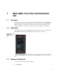
MOD 30ML Front Face Familiarization Lab 1 1.1 Foreword Many processes involve flow control loops, whether they are in the food, pharmaceutical, chemical, pulp & paper, mining or virtually any of the industries served by MODCELL Multi-loop Processors. This lab is designed to help you learn the basic features of the Application Builder, as well as how to easily demonstrate configuration of a PID loop. 1.
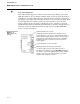
Training Manual MOD 30ML Front Face Familiarization Lab 1.4 2. 1 x Memory module (2010PZ10000A) marked FACEPLATE (and loaded with the FACEPLAT.CDB file) 3. 1 x Small flat screwdriver Instructions 1.4.1 Before you power up the instrument Step 1 Procedure Make sure the SERV/RUN switch under the front face is set to the RUN position Comments This ensures that after a download the database will be able to run. This switch is located behind the front panel in the NEMA 4 option.
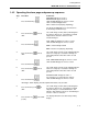
Training Manual MOD 30ML Front Face Familiarization Lab 1.4.2 Operating the alarm page and power-up sequence Step 1. Procedure Comments MEM MOD will appear on line 1 WRTPROT will appear on line 2 UAK and RET will appear on lines 3 and 4 UAK = Unacknowledged alarm RET = Return to loop display (Operating) Press the Alarm Key The AUTO and MANUAL keys now function as Acknowledge and Return keys. 2. Press the Auto key UAK. next to 3.
Training Manual MOD 30ML Front Face Familiarization Lab Note: Active Diagnostics An unacknowledged diagnostic condition is always indicated by flashing of the alarm LED. The indication may also include a flashing display and a beep signal depending on configuration. A dedicated alarm display provides information on all active diagnostics. An example of the display with control key information is shown in the next figure.
Training Manual MOD 30ML Front Face Familiarization Lab 1.4.3 Operating the Loop display Left Bar will display the Process variable Middle Bar will display the setpoint Right Bar will display the control output Line 1 will display the loop tag = FIC-100 Line 2 will display the process input and units = 0.
Training Manual MOD 30ML Front Face Familiarization Lab 1.4.5 Operating the Ramp keys Objective: To manually set the control output to a value of 24.8%. During the following procedure, if the time between key strokes is greater then 10 seconds, then the display will automatically change back to the operating loop display. If this is the case, simply press either the UP or DOWN key and select the character you wish to change using the FST and SLO keys. Step 1.
Training Manual MOD 30ML Front Face Familiarization Lab 1.4.6 Operating the Scroll key Step 1. Procedure Press the SCROLL key Comments Line 5 changes to display SP (Setpoint) You can use the method described in section 1.4.5 - OPERATING THE RAMP KEYS to change the value of the setpoint. 2. Press and hold the SCROLL key 3. Press the UP key twice to change the bottom number to 2, and then press ENT 4.
Training Manual MOD 30ML Front Face Familiarization Lab 1.4.7 Checking the Communication setup Objective: Determine the Modbus address and communication parameters of this instrument Step 1. Procedure Press and hold the TAG key 2.
Training Manual MOD 30ML Front Face Familiarization Lab Communication Information: Modbus Address Baud Rate Stop bits Built-In Comm Enabled 1-9
Training Manual MOD 30ML Front Face Familiarization Lab Notes: 1 - 10
2 2.1 MOD 30ML Operation Lab 2 Foreword MOD 30ML can perform complex continuous control as well as discrete control. The Sequencer block in the MOD 30ML can be used for executing complex batch and sequencing control. Custom displays can be built for information and operation of the advanced control. 2.2 Objectives In this lab we will download a batch control strategy from the memory module to the MOD 30ML controller and run the batch from the custom displays.
Training Manual MOD 30ML Operation Lab 2 Figure 2 .1. Batch Temperature Cycle During the heat stage of the batch cycle, a cascade temperature loop is used to control temperature. At the time the sequence enters the heating step, the setpoint of the master controller is ramped to the reaction temperature; the master controller measures the product temperature while the slave measures jacket temperature. At the cooling stage, the setpoint is ramped back to the cool setpoint. Figure 2 .2.
Training Manual MOD 30ML Operation Lab 2 • Manual advance of sequence Initial Conditions: 1. Batch AUTO, OFF (Note: once the batch has been started, Line 2 will indicate the Time in Step for each step. If the batch is put into manual mode, Line 2 will display Manual. The “time in step” timer does not stop if the batch is put into manual. However, if you manually advance to another step, the step timer restarts). 2. RECIPE 1 selected 3. Temperature setpoint LOCAL 4. Level 0.0” H2O 5.
Training Manual MOD 30ML Operation Lab 2 2.3 Instructions 2.3.1 Download Reactor database from the memory module: Step 1 Procedure Make sure the SERV/RUN switch under the front face is set to the RUN position Comments This ensures that after a download the database will be able to run. This switch is located behind the front panel in the NEMA 4 option. You will need to remove the instrument from its housing to set it.
Training Manual MOD 30ML Operation Lab 2 2.3.2 Scroll through the displays: Step 1 Activity The first display as shown in the previous page is the main batch display. This is the display where we will start the batch. But before that, we will scroll through the other displays to get an overview. Look For Note that the batch is in AUTO mode and is not running right now (OFF). The setpoint is in local (LOC) mode. 2 Press the TAG key once to go to the TIC-100 temperature control loop display.
Training Manual MOD 30ML Operation Lab 2 You can display and manipulate on one instrument, all process and calculated values associated with the process unit, including both sequence and continuous control. 2.3.3 View the Tuning displays and change the batch recipe: 3 4 Display tuning pages for TIC-100 and TIC-101.
Training Manual MOD 30ML Operation Lab 2 2.3.4 Run the Batch: 5 Press the TAG key to return to main Batch display Press AUTO key to start the batch Batch status changes to RUN See the next figure. Setpoint status changes to REMOTE Step indication on Line 6 changes to START and then to FILL. Figure 2 .6.
Training Manual MOD 30ML Operation Lab 2 7 Return to main batch display and observe step. 8 When controller has entered HEATUP step, scroll to temperature control displays (TIC-100 and TIC101) Cascade control for temperature is now active Master controller setpoint value ramps to 111ºF. Read the process value of TIC-100. This will also ramp to 111 def F in a couple of minutes Refer to the next figure. Figure 2 .8.
Training Manual MOD 30ML Operation Lab 2 2.3.5 Switch the batch control modes: 9 When batch cycle has entered HOLD step, return to main batch display Press MAN key to put batch cycle in manual control Batch status on line 2 changes to MANUAL. STP indication appears next to Scroll key Figure 2 .9. Batch in Hold 10 Press STP key (scroll key) to scroll to COOLDOWN Press MAN key again to return batch cycle to automatic control Batch time shows on line 2.
Training Manual MOD 30ML Operation Lab 2 11 Scroll to TIC-100 display Temperature setpoint ramping down to cool setpoint 12 When batch cycle has entered DRAIN cycle, scroll to level display Falling reactor level as vessel is drained 13 Scroll back to the main display When drain cycle is finished (level has returned to 0) and current step shows as END. Press the MANUAL key, change the step to OFF, and press the AUTO key to return the batch to OFF status.
Single Loop Template Lab 3 3.1 Foreword Many processes involve flow control loops, whether they are in the food, pharmaceutical, chemical, pulp & paper, mining or virtually any of the industries served by MODCELL Multi-loop Processors. This lab is designed to help you learn simple PID loop configuration from the MOD 30ML front face. 3.
Training Manual Single Loop Template Lab 3.3 Instructions 3.3.1 Power up the controller 1. We will remove the memory module if any from the controller. Loosen 2 screws on Faceplate on controller and remove Instrument from housing. Remove Memory module from Instrument. Return Instrument to housing. Removing the memory module will prevent downloading of configuration from the memory module in case the instrument is powered up. 2. Power-up Instrument if it is not already powered up. 3.3.
Training Manual Single Loop Template Lab Figure 3 .3. MOD 30ML Alarm CLeaRed Alarm • The next figure shows an active alarm. Figure 3 .4.
Training Manual Single Loop Template Lab 3.3.3 Front face Configuration Map: The front face configuration map shows an overview of the menus available front the front of the MOD 30ML controller. The major menu items at the top level can be scrolled through, by selecting NXT from the front face while DEVICE is displayed on line 1. 1. DEV STAT – This menu allows you to access the following sub menus: (The sub menus are reached by pressing the DOWN arrow from the main menu.
Training Manual Single Loop Template Lab 3.3.4 Scroll through the top level front face menus: Step 1 Procedure Press and hold TAG key until *DEVICE* is displayed on line 1. Comments See the figure below: 2 Press the NXT (the key next to the NXT display on the front face). 3 If you pressed any other key and do not know where you are, press and hold the TAG key until *DEVICE* is displayed at the top. See the menu items changing in line 6. 3.3.
Training Manual Single Loop Template Lab 4 Press ENT again to enter Configuration mode. You will be in DEV STAT menu mow. See the sequence of figures below: Lines 1 and 2 will display DEV STATE and INSTATE (Instrument state). Line 6 will display RUN indicating that the controller is running a valid database. 5 Press the NXT key until COMMANDS is displayed on line 2. You can issue commands to the controller from this menu. Figure 3 .6. 3-6 6 Press the DOWN key once.
Training Manual Single Loop Template Lab Figure 3 .7. 13 Acknowledge UNCONFIG alarm by pressing the ALARM key and the AUTO key. 14 Press RET key 15 If line 2 displays DEL MAIN go to Step 17 otherwise continue at step 16. 16 Press DOWN and NXT key 2 times. Press DOWN key again. Press NXT key 5 times. 17 Press NXT key The Alarm display will show INST UNCONFIG saying that the instrument is unconfigured.
Training Manual Single Loop Template Lab Figure 3 .8. 3-8 18 Press NXT key, then press the UP key You are exiting the COMMAND section 19 Press NXT key XTIMES is displayed on Line 2. Scan groups 1 through 5 are user-defined intervals for loops. The fastest group has the highest priority. The lower numbered group has a higher priority if the interval is the same. Scan group 6 is a system group. Scan groups 7 to 9 are communications groups. 20 Press NXT key TIME is displayed on Line 2. Current time.
Training Manual Single Loop Template Lab 3.3.6 System Compound – Load Defaults: 1 Press NXT until TEMPLATE is displayed on line 6. See figure below: 2 Press DOWN 3 Press DOWN LOAD DEFAULTS will be displayed on lines 1 and 2. We use the default template as a starting point for creation of a database. Default values are the basis for what is shown in the Operation manual. “VERIFY LOAD” will be displayed on lines 1 and 2 Figure 3 .9.
Training Manual Single Loop Template Lab Figure 3 .10. 3.3.7 System Compound – Edit System Template: We will change the System tag name and the system scan group 2 scan interval in this section. 1 Use the Arrow keys to scroll through INSERT, EDIT, and LIST. DO NOT PRESS ENTER INSERT is used to add a user compound after system compound.
Training Manual Single Loop Template Lab Figure 3 .11. . 7 8 Press NXT to access System Scan Groups. Press DOWN Scan groups defined update intervals for loops. SYSTEM SCANGRPS should be displayed on lines 1 and 2. See the figure above. The arrow key will change the Scan Group time by 50 mSec steps. Scan groups 1 through 5 are user defined intervals for loops Leave at 0:00.100. The fastest group has the highest priority.
Training Manual Single Loop Template Lab We will change the system tune and configuration passwords in this section. 1 Press DOWN TUNE PASSWORD is displayed on lines 1 and 2. 2 Press UP key to set 1 as password then press ENT. Enter a number required to access tuning parameters. 3 Press NXT CONFIG PASSWORD is displayed on lines 1 and 2. 4 Press UP arrow to set 2 as Configure password.
Training Manual Single Loop Template Lab Next, we will change some of the system alarm settings. 1 Press DOWN DIAGNSTC RATE is displayed on lines 1 and 2. FAST = off 100mSec, on 300 mSec. SLOW = off 250mSec, on 750mSec. We will accept the FAST rate. Alarm indication rates apply to light, display and beeper. Alarms are: unacknowledged diagnostics, high or low process and deviation conditions, and input quality 2 Press NXT DIAGNSTC FLASH is OFF. OFF = flashing is disabled.
Training Manual Single Loop Template Lab 3 - 14 9 Press NXT HIGH PRI BEEP is OFF. OFF = beeping is disabled ENABLE = beep on alarm 10 Press NXT LOW PRI RATE is SLOW. FAST = off 100mSec, on 300 mSec SLOW = off 250mSec, on 750mSec 11 Press NXT LOW PRI FLASH is OFF 12 Press NXT LOW PRI BEEP is OFF. 13 Press NXT SYSTEM appears on line 1; Lines 2 and 6 are blank 14 Press UP End of SYSTEM ALARMS 15 Press NXT End of SYSTEM functions.
Training Manual Single Loop Template Lab 3.3.8 Single Loop PID control template setup: When you loaded defaults, you automatically created a “blank” loop tag which was given the name CTAG01. We will now edit this loop. 1 Press UP arrow twice to select EDIT on line 6 and press ENT TAG ID STRING on lines 1 and 2. CTAG01 on line 6. 2 Press UP arrow to change tag characters. While display is flashing, press UP until F is displayed DO NOT PRESS ENTER 3 Press NXT .
Training Manual Single Loop Template Lab 11 Figure 3 .15.
Training Manual Single Loop Template Lab 3.3.9 Process Input Setup 1 Press NXT PROC INP will be displayed on line 2. We are entering the process input setup for our PID control loop. 2 Press DOWN This takes you into the process input definition menus. SLOT will be displayed on line 2. 3 BI 1 AIN is the default input. We will accept this. This is Built-In Analog Input 1.
Training Manual Single Loop Template Lab key to set the range at 200. Then press ENT Significant Digit to flash, indicating you can change that digit. Each time you press the FST key the flash digit will move one digit to the left. Pressing one of the arrows will cause the flashing digit to ramp up or down. Press NXT EU LABEL will be displayed on line 2. 13 Using the UP/DOWN keys and NXT key, spell out GPM Then press ENT Up to a 4 character label to appear after process input value.
Training Manual Single Loop Template Lab 16 Press NXT 17 Set line 6 at 220. Then press ENT 18 Press NXT until line 2 and 6 are blank and only the up arrow is on 19 Press UP 20 Press NXT HI QUAL is displayed on line 2. Result is set BAD if it goes above this value. High quality must be higher than the low quality value This completes the Process Input section. SETPT will be displayed on line 2. Figure 3 .19.
Training Manual Single Loop Template Lab 3.3.10 SETPOINT Setup 1 Press DOWN to enter setpoint section. 2 Press NXT until SETPOINT HI LIMIT is displayed on lines 1 and 2. 3 Set the high limit at 200. Then press ENT. 4 Press NXT until INITIAL VALUE is displayed. 5 Set the value at 100.0. Then press ENT. Setpoint value when configuration is complete. 6 Press NXT until lines 2 and 6 are blank and only the up arrow is on.
Training Manual Single Loop Template Lab 3.3.11 CONTROL Setup 1 Press DOWN to enter control section. This takes you down into the Control menus 2 ALGO TYP is displayed on line 1. Gain (1st Character): What is the ALGO TYPE ? O = Off P = On Process E = On Error Reset (2nd Character): O = Off S = Standard M = Micro-Scan Pre-Act (3rd Character): O = Off P = On Process E = On Error Manual Reset (4th Character): O = Off E = Enabled Figure 3 .21. Figure 3 .22.
Training Manual Single Loop Template Lab 3 - 22 3 Press NXT until “GAIN” is displayed on line 1. Set Gain at 0.65. Then press ENT. 0.01 to 125.0 Proportional response in a fixed gain controller. 4 Press NXT, set Reset at 30.00 then press ENT 0.01 to 125.0 Reset in repeats per minute. 5 Press NXT until INITIAL MODE is displayed on lines 1 and 2. 6 Set Mode to AUTO. Then press ENT 7 Press NXT until lines 2 and 6 are blank and only the up arrow is on.
Training Manual Single Loop Template Lab 3.3.12 OUTPUT Setup 1 Press DOWN to enter output section 2 Leave the default value of BI1 AOUT in place 3 Press NXT 4 Press NXT NONE, BI1 AOUT, BI2 AOUT, and S01 to S11. Only available outputs are listed. OUTPUT LO SIGNL displayed. 0% of the output range. OUTPUT HI SIGNL displayed. 100% of the output range Figure 3 .23. 5 Press NXT until OUTPUT LO LIMIT displayed 6 Set limit to 0.0.
Training Manual Single Loop Template Lab Figure 3 .24. 3 - 24 8 Set limit to 100.0 and press ENT 9 Press NXT until Line 2 displays OUTPUT INIT VAL 10 Change the initial value to 50 11 Press NXT until COMPOUND is displayed on line 1 12 Press UP This completes the output section. 13 Press NXT This takes you to the ALARM section of the configuration tree. We will not setup any process alarm in this lab. 14 Press NXT COMPOUND is displayed on line 1 and LIST on line 2.
Training Manual Single Loop Template Lab 3.3.13 Install the edited template 1 Press UP CMP LIST FIC 100 is displayed on lines 1 and 2. 2 Press NXT CMP LIST is displayed on line 1; lines 2 and 6 are blank 3 Press UP EDIT TEMPLATE displayed on lines 1 and 2. 4 Press NXT INSTALL TEMPLATE displayed 5 Press DOWN. Select INITWARM INSTALL TYPE displayed. 6 Press ENT This compiles your configuration and loads it into runtime memory. You should now see the FIC-100 display.
Training Manual Single Loop Template Lab 3 - 26
4 4.1 MOD 30ML Diagnostics Lab Foreword The MOD 30ML provides a comprehensive way of displaying active diagnostic information as well as a history of events. Events are a combination of alarms and information only activities that the instrument had gone through. 4.2 Objectives We learned how to read the active diagnostics and acknowledge them in Chapter 1. In this lab we will read the diagnostics history by using the Event Viewer available from the front-face.
Training Manual MOD 30ML Diagnostics Lab 4.4 Instructions 4.4.1 Event Viewer The System Event block stores diagnostics reported by the data base blocks. Viewing the system event queue provides data on all diagnostics that have occurred since the current data base was down loaded or the queue was cleared. The queue contains both informational and diagnostic data. The data for each event in the queue is displayed on two pages.
Training Manual MOD 30ML Diagnostics Lab page1 6 Press NXT to display the next event in the queue. Page 1 of the next event will be displayed next. 7 Use the block type and event code, to locate the event description and recommended action listed in Section 7 of the Maintenance manual.
Training Manual MOD 30ML Diagnostics Lab 4.3.2 Clearing events from the event history: The controller can store up to a maximum of 1000 events in its queue. The default queue size is 50 events and is configured in the SE (System Event) block of the database. You can configure what goes in to the queue. By default, the following are entered in the event list: (see the next figure) 1. 2. 3. 4. 5. 6.
Training Manual MOD 30ML Diagnostics Lab 2 Press DOWN key once. If PASSWORD is not displayed on line 2, go to step 5. Otherwise continue with Step 3. 3 Use UP key three times to select the PASSWORD and then use ENT to enter. See the next set of figures Lines 1 and 2 will display CURRENT LEVEL and Line 6 will display CONFIG indicating that the controller is in configuration mode. 4 Press ENT again to enter Configuration mode. Lines 1 and 2 will display DEV STATE and INSTATE (Instrument state).
Training Manual MOD 30ML Diagnostics Lab 4-6 6 Press the DOWN key once. CLR Q is displayed on line 2. 7 Press the UP arrow. YES will be displayed. 8 Press ENT (SCROLL key). The Events queue will be cleared and line 6 will display NO again. 9 Press the TAG key. The DEVICE page will be displayed. 10 Pres the TAG key again. Your runtime display will be displayed.
Training Manual MOD 30ML Diagnostics Lab 4.5 Instrument Shutdown 4.5.1 Force a shutdown Step 1 Procedure Make sure the SERV/RUN switch under the front face is set to the RUN position Comments This ensures that after a download the database will be able to run. This switch is located behind the front panel in the NEMA 4 option. You will need to remove the instrument from its housing to set it.
Training Manual MOD 30ML Diagnostics Lab 4-8 7 Press the SCROLL key ONCE. The PID setpoint will be shown on line 6 and the text “SP” on line 5. 8. Press the SCROLL key twice more and wait for a few seconds. The runtime PID display will disappear and FAILURE will be displayed on line 1 with an audible continuous alarm. At this point, you cannot operate the PID loop or use the controller. This is an indication that the controller is in SHUTDOWN mode.
Training Manual MOD 30ML Diagnostics Lab 4.5.2 Read the shutdown information and acknowledge it: Step 1 Procedure The first step in reading the shutdown info is to cycle power the controller. Power down the controller and then power it. Comments After power up the DEVICE display will come up. The instrument will be in default mode and Line 3 will display DEF as shown in the first figure below. There will be diagnostic alarms and the RED LED will be flashing.
Training Manual MOD 30ML Diagnostics Lab 3 Press the TAG button after viewing and acknowledging the alarms. The instrument will display the DEVICE display. Line 6 will show DEV STAT. See the middle picture in the next figure. 4 Press the DOWN arrow to enter the DEV STAT menu. The first page in this menu shows the Instrument’s state as shown in the last picture in the next figure. The device state is DEFAULT after a SHUTDOWN. 5 Press the NXT to view the SHUTDOWN page.
Training Manual MOD 30ML Diagnostics Lab 7 Press the NXT key to view Pages1, 2, 3 and 4 and record the information Shutdown page 2 displays the time and date of the shutdown. 8 Press NXT to go to Page 5 Page 5 displays ACK SD and NO on lines 2 and 6 respectively. See the next figure: Press the UP/DOWN arrow to show YES on line 6 and then press the key next to ENT on the display This will acknowledge the Shutdown and line 6 will display NO again. Line 3 will now change to display RUN.
Training Manual MOD 30ML Diagnostics Lab Notes: 4 - 12
5 5.1 ViZapp Setup Lab Objectives In this lab we will setup the ViZapp Software on your computer. After completing this lab you should know how to install and setup ViZapp on your computer. 5.1.1 System requirements: The following computer configuration is the minimum recommended for running ViZapp: • 1GHz CPU with 512 MB RAM • 500 MB of available hard disk space • 4x CD ROM Drive • 1024x768, 256 color video card and monitor • Microsoft Windows 2000, Windows XP or Windows NT 4.0.
Training Manual ViZapp Setup Lab 5.2 Instructions: The following procedure explains how to install ViZapp on your computer. ViZapp Setup will install a Microsoft Software component called MDAC (Microsoft Data Access Components) if the minimum required version was not present in the system already. This program is required by the ViZapp Reports. MDAC is also installed by other Microsoft and third party programs. ViZapp also requires another software package called OPC Core Components.
Training Manual ViZapp Setup Lab Figure 5 .2. Run dialog box 2. Click on ViZapp Setup, acknowledge the license note and the introductory screen will display briefly while installation is initiating. Figure 5 .3. ViZapp Setup Figure 5 .4.
Training Manual ViZapp Setup Lab 3. The setup will display the Welcome dialog box as shown below. Click on Next to continue. Figure 5 .5. ViZapp Setup Welcome 4. The MICROMOD Software License Agreement will appear next and will display the legal information about using the ViZapp Software. Click on Yes if you accept the agreement. Clicking on No will terminate the Setup. Refer to the next figure. MICROMOD Software License Agreement is a legal document. Please read it carefully before clicking on Yes.
Training Manual ViZapp Setup Lab Figure 5 .7. ViZapp Setup – Information 5. Customer Information: The User Information dialog box will be displayed next as shown below. Type your name and company name. Note that ViZapp versions prior to 3.01 also required a serial number to be entered. This serial number can be found on the CD case or the ViZapp package you received. Click on Next to continue. Figure 5 .8. ViZapp Setup – Destination Location 6.
Training Manual ViZapp Setup Lab • Click on OK to continue. Figure 5 .9. ViZapp Setup – Choose Destination 7. The Data Root Directory dialog box will be displayed next as shown in the next figure. We will choose the default location for the data files. Click on Next to continue. If you want to specify a different default folder for your data files (configuration files such as workspace, project, database files etc.
Training Manual ViZapp Setup Lab 8. Select Components for installation: The ViZapp Software package consists of the main software and a few options. You can choose the options at the time of setup. The Select Components choices will vary depending on which version of ViZapp is being installed. By default, all available options are selected. Note that selecting On-line Documentation installs all documentation onto the hard drive.
Training Manual ViZapp Setup Lab Figure 5 .12. ViZapp Setup – Select Components • Click on Next to continue. Figure 5 .13. ViZapp Setup – Program Folder 10. 5-8 Setup will display a message box as shown in the next figure. The OPC Core Components will be installed in your computer.
Training Manual ViZapp Setup Lab Figure 5 .14. ViZapp Setup – Program Folder • Click on OK to continue. • The OPC Core Components setup will also install .NET components for OPC if you have the .NET framework from Microsoft already present in the system, though the .NET framework is not required for ViZapp. Click on OK to continue. Figure 5 .15. ViZapp Setup – Program Folder 11. If you have a pre-existing Gallery file in the installation folder, the dialog box shown below will be displayed next.
Training Manual ViZapp Setup Lab • If you chose to rename the existing file, the following Rename Gallery dialog will be displayed. You can type a name for the old gallery file. Click on Next. See next figure: Gallery File: The gallery is a library of configuration compounds (collection of function blocks configured for a specific functionality), smart symbols and static symbols that can be used in your applications.
Training Manual ViZapp Setup Lab Figure 5 .19. HardLock Device Driver Figure 5 .20. HardLock Device Driver • If you have a USB style key on you computer, remove it before continuing. Click on Next on the Welcome dialog in the HardLock Device Driver Installation. If you do not have a HardLock key, you may click Cancel on this dialog to skip to the Rainbow driver installation. • The HardLock device driver installation will start and the files will be installed.
Training Manual ViZapp Setup Lab Figure 5 .22. HardLock Device Driver Setup • The Finished dialog box will be displayed after the device driver is installed. See the figure below: • Click on the Finish button on this dialog box. Figure 5 .23. HardLock Device Driver Setup 13. The Rainbow device drivers will be installed next. See the next figure: Figure 5 .24. Rainbow Device Driver Remove any USB keys that are connected to the computer before continuing. • 5 - 12 Click on OK to continue.
Training Manual ViZapp Setup Lab Figure 5 .25. Rainbow Device Driver • The following will be displayed if you are installing the driver for the first time on a Windows XP system with a firewall. • When the Sentinel driver installation is complete, ViZapp setup will continue. Figure 5 .26.
Training Manual ViZapp Setup Lab Figure 5 .27. ViZapp Setup 14. The ViZapp setup will start now and will display a progress bar as shown above. After the ViZapp Setup copied all the required files, the following Information box will be displayed. The MicroMod Systems Software CD contains all the technical documentation in Adobe PDF format. If your system does not have Adobe Acrobat Reader installed already, you can install it from the CD after the ViZapp Setup completes. Figure 5 .28. ViZapp Setup 15.
Training Manual ViZapp Setup Lab Figure 5 .29. ViZapp Setup 16. After the files are registered, the setup will display a message ass shown in the next figure. Refer to the License admin section of this manual to add licenses to the software. Figure 5 .30. ViZapp Setup Figure 5 .31. ViZapp Setup 17. ViZapp setup will now be complete and a dialog box as shown in the next figure will be displayed. Figure 5 .32. ViZapp Setup – Setup Complete • Click on Finish to complete the installation.
Training Manual ViZapp Setup Lab 5 - 16
PID Loop Lab 6 6.1 Foreword Many processes involve flow control loops, whether they are in the food, pharmaceutical, chemical, pulp & paper, mining or virtually any of the industries served by MODCELL and MOD 30ML. This lab is designed to help you learn the basic features of the ViZapp configurator, as well as how to easily learn/demonstrate configuration of a PID loop. 6.
Training Manual PID Loop Lab 6.3 Instructions Follow these instructions step-by-step to configure a simple PID loop: 6.3.1 Getting started 1. Launch ViZapp. Select Programs from the Windows Start menu. Select ViZapp from the menu. The ViZapp configurator will launch as shown in the next figure. As you will notice, the configurator will be blank with no workspace loaded on the screen. Figure 6 .2. ViZapp Configurator • 2. Figure 6 .3.
Training Manual PID Loop Lab • This will open the New dialog box as shown in the next figure. There are 2 tabs (sections) in this dialog box and it displays the Project tab as default. • Click on the little button next to the Location field to open the Browser for Folder dialog as shown in the next figure: • Select the C: drive from this folder and select on it by double-clicking on it. See next figure: • The New dialog box will redisplay Figure 6 .4. New Project Figure 6 .5.
Training Manual PID Loop Lab Figure 6 .6. New Project • 6-4 Type the name CLASS for your project in the name field. Notice that the name of the location for this project changes to C:\Class. It creates a folder under the C: drive (or any other drive you choose) automatically. All project files and the instrument and display documents will be saved in this folder. This makes project portability easier. • Click on the option Create a new Workspace. This will create a new workspace for us.
Training Manual PID Loop Lab Figure 6 .7. Class Workspace 3. • The left frame shows the project tree. The Workspace is at the root of this tree and contains the Project, and other components such as Event Log and Components. • The newly created workspace is given the same name as that of the project. The project sub-tree or branch contains the components Security and Tags. With what we have above, we have only created an environment to configure instrument database and display files.
Training Manual PID Loop Lab Figure 6 .8. New Document • The New dialog box shows the Document tab now. Select the type MOD Function Block diagram by clicking on it and then type the name PIDLAB for the document in the Name field. • This document will be created in the project folder \class automatically and will be added to your Class project by default. See figure above. When you create a new project, a file with the project name and file extension .APRJ will be created.
Training Manual PID Loop Lab Figure 6 .9. Instrument Versions • Select MOD 30ML 2 from this list as our instrument version by clicking on it and then click on the Close button. • The Configurator will redisplay as shown below. The instrument database will be opened on the right frame and the default blocks (IF, SE, ST and DIF) for the MOD 30ML database will be loaded. • Notice that the newly created document PIDLAB is shown in the project tree attached to the Project Class.
Training Manual PID Loop Lab 4. Let us first configure a scan group: There could be as many as five scan groups in an instrument database. The control loops (database blocks connected together) are grouped into Loop Compounds. The Loop Compounds can be assigned to any of these scan groups. All the blocks and compounds in a particular scan group will be executed at the same scan rate configured for the group.
Training Manual PID Loop Lab • Outgoing • Connect map • Shape Configuration parameters related by common nature are grouped into these tabs. This helps to display of information in a logical manner. Most fields under these tabs contain default values that need not be changed. 5. Add a loop compound. We will configure our control loop inside this loop compound. • Select the Loop Cpd (Loop compound) block from the Algorithms window add it to the document.
Training Manual PID Loop Lab Figure 6 .13. Loop Compound Properties • Select Properties from the menu. The Algorithm Properties of the Loop Cpd block will be displayed next as shown in the next figure. • Type Control in the Name field. • Type a description "This compound is for the Flow Control Loop" • Click on OK to close the Properties. Figure 6 .14. Loop Compound Properties 7.
Training Manual PID Loop Lab • Right-Click on the Control compound (Loop compound you just named) again and select Open compound at the bottom of this menu. • The loop compound will open as shown below and will have a Loop block (LP) by default. Figure 6 .15. Loop Block A loop compound is a compound or group that contains a loop block. You configure other blocks and compounds inside the loop compound. The compound can be added to one of the five scan groups defined in the Interface block.
Training Manual PID Loop Lab Figure 6 .16. Loop Block • 9. Close the Loop block by clicking on the OK button. Configure the PID loop shown in Figure 6.17: • Let us start doing this by adding the necessary algorithm blocks to the Loop Compound on the workspace on the right frame.
Training Manual PID Loop Lab Figure 6 .17. Algorithm blocks in the Loop Compound 10. Resize and move these blocks to fit them on the database workspace. • Select a block by clicking on it. The selected block will have handles around it. See figure below: • Move the block with the left mouse button pressed on it and by moving the mouse. • Resize the block by dragging one of the handles (corner or side) Figure 6 .18.
Training Manual PID Loop Lab 6.3.2 Configuring the blocks: 11. Let us configure these blocks next. • Configure the Analog Input block. • Double-click on the AIN block to open its Properties menu as shown below: • Type FT-100 as the name. • Select Current as the Input type from the drop-down menu. • Type the Input number as 2 and Description as shown in the above figure. This is the built-in input 2 of the MOD 30ML.
Training Manual PID Loop Lab Figure 6 .20. VCI Properties 12. • Type the name and description for this block as shown above. Move the cursor to the Linearization Type field and click on the down arrow. Select Modifies Square Root as the type from the drop-down menu. This will compensate for errors at very low flow measurements. • Change the Range to 0 to 200 and Quality limits also to 0 to 200. The measured signal (4-20mA or 1-5V) will be interpreted as 0 to 200 flow units.
Training Manual PID Loop Lab • Select File – Save All from the menu bar. This will save the document, the project file and the workspace file. Note that Save only saves the currently opened document. Unless you have made changes in other documents that you do not wish to save, you may select Save-All instead. 13. Continue configuring the other blocks. Double-click on the PID block. Give the block the tag name FIC-100. • Change the Process Input range to 0 and 200.
Training Manual PID Loop Lab Figure 6 .23. PID Properties 14. • Change the Setpoint low and high limits to 0 and 200. • Click on the other tabs at the top (Control, Modes, Options etc, to view different pages of the PID block. • We will accept default values for the other parameters. Click on OK to close the PID block.
Training Manual PID Loop Lab Figure 6 .24. Aout Properties 6 - 18 • Specify the Output number as 2. This is built-in analog output two. • The source range of 0 to 100 from the PID block will be converted to 4 to 20mA output. Refer to the above figure. • Click on OK.
Training Manual PID Loop Lab 6.3.3 Connecting the blocks: 15. The next step is to connect the blocks together to realize the control loop shown in Figure 6.1. • Click on the Multi-Segment connection item on the Algorithms menu to enable connection mode. See figure below: • Move to the workspace on the right and click on the AIN block’s (FT-100 – source block) output connection point as shown in the next figure. Notice that moving the cursor over the output of a block, shows a fly-by box.
Training Manual PID Loop Lab • Click on the input of the VCI block. See the figure above. • The connection will now be complete. The connection line will have the source name and destination name displayed right on it as shown in the above figure. Figure 6 .28. Connecting blocks The input connection points are on the left side of the blocks and the output connection points are on the right hand side. There might be more than one input or output for each block.
Training Manual PID Loop Lab Figure 6 .30. Right Angle connection • 17. Click on the output point of the FY-100 block. This point is the result of the FY100 input function block. The fly-by box will say R when you click on the output. Drag the line to the input point of the PID block and clock on it (PVI) to complete the connection. Connect the output of the PID (FIC-100) to the INPUT of the AOUT (analog output) block with the right angle connector as shown below. Figure 6 .31.
Training Manual PID Loop Lab Figure 6 .32. Cancel Connection 18. Add the blocks from the Component Gallery: • From the top menubar, select Project/Gallery/Component Gallery • When the Component Gallery dialog box appears, select the Compounds tab. A library of pre-configured Compounds, or groups of algorithm blocks, appears. Figure 6 .33.
Training Manual PID Loop Lab Figure 6 .34. Compound Library • Move the cursor to the PID Display compound and either double-click, or select it and then select the Export button. The Component Gallery dialog box closes and a set of blocks is placed in your workspace. The blocks are highlighted with small green boxes. Figure 6 .35.
Training Manual PID Loop Lab • Click elsewhere on the screen to deselect them. The loaded blocks include a Display (DISP) block, a Tuning List block (TL) and two text boxes. The text boxes contain information about the compound. You can read the text and move them to a different area of the screen or delete them from the screen. • Delete the TL (Tuning List) block from the screen. Delete also the connection from the TL block to the display block.
Training Manual PID Loop Lab • Using the Multi-Segment connector, click on the PID block and select PVI from the resulting dialog box. Double-click on PVI or select and click on the OK button. • Drag the cursor over the Display block and click. Select process from the resulting dialog box. See the next figure: Figure 6 .38.
Training Manual PID Loop Lab Figure 6 .39. Choose parameter for connecting 6 - 26 • The connection between the Process variable in the PID block and the Dsiplay Block input called “process” is now complete.
Training Manual PID Loop Lab Figure 6 .40. Connections from PID block parameters to Display block inputs 20. The display compound from the Component Gallery is set up for 0 to 100. This must be changed to match the PID block that we configured for 0 to 200. We must also designate a display tag. • Double-click on the Display block. In the resulting dialog box, type FIC-100 in the Display Tag field (overwrite the PID-100). Figure 6 .41.
Training Manual PID Loop Lab This tag must be unique to this display. It can also be used as the tag name that appears on the front face. The default DISPTAG in Line 1 of the Intial Values causes the value or name typed in the Display Tag field to appear on Line 1 of the display on the front panel. For more detailed information on display building, refer to IB-1800R-SCR, Display Guide.
Training Manual PID Loop Lab Figure 6 .43. Changing engineering unit range for process line display • Select the OK button at the bottom of this dialog box. • Repeat this process for the following formats: • 21. • setpointL • processB Close the Display Block with the OK button at the bottom of the dialog box.
Training Manual PID Loop Lab Figure 6 .44. Closing Compound 22. • Select Close Compound at the bottom of this menu. • You should be back in the original page where the IF, DIF and SE blocks are located. Add the Display Tag to the Display Interface Block: The next step is to add the display tag of the display block we configured in the previous steps to the display list in the display interface block.
Training Manual PID Loop Lab • Click on the New button on this block as shown in figure below: • A text edit box will appear in the area below and you will see a text edit cursor blinking. • Type the name of your display tag (FIC-100). Refer to the next figure. • Click on the OK button when you are done. Figure 6 .46. Closing Compound a If you had more than one display blocks in your configuration, you will need to add their display tags in the DIF block as explained in the above step.
Training Manual PID Loop Lab Figure 6 .47. Closing Compound 23. 6 - 32 Add a Configured list block and add signals to it: Next we will need to add parameters to pass on the Extended Modbus that can be served by the XModbus OPC Server or a XModbus Device Driver to Client Software packages like HMI/HSI clients. This is needed only if you connect your controller to a host computer. If your controller will be stand-alone, you do not need to send parameters over Modbus/ XModbus.
Training Manual PID Loop Lab Figure 6 .48. CL block • Click on the Add button on this page/tab. • The Browse dialog will be displayed as shown above and will list all the blocks and compounds that are present in your document as a tree structure. These will be shown with box icons next to them meaning that there groups and there are further items inside each group. • You must be seeing the Loop Compound Control also listed in this dialog. Figure 6 .49.
Training Manual PID Loop Lab • Double-click on this item to open it. The tree will expand and will display the blocks inside the Control group. • Click on the item FIC-100. This will display the attributes of the FIC-100 (PID block) in the box on the right. • Click on OP (PID output) and then on the Add button at the bottom to add the PID output to the CL block. DO not hit the OK button ! • Select SP, PVI, SPMS and OPMS from this list and add them in the same way. Figure 6 .50.
Training Manual PID Loop Lab Figure 6 .51. CL block • a Click on OK on the Browse dialog. This will redisplay the CL block Properties as shown above. The Inputs Tab will now display the attributes you just added. The attributes will be displayed with full source path name of the connections. An alias can be entered by selecting an item and typing in any alias name. This name will then be displayed instead of the block tag and attribute name. 24.
Training Manual PID Loop Lab Figure 6 .53. CL block aliases • Click on OK when you are done with the CL block. The next step is to setup communications. The MOD 30ML can communicate using Modbus or ICN. If you are using Modbus, proceed with the next section. If you are using ICN, skip the next section and proceed to the following section, Setting up communications for ICN.
Training Manual PID Loop Lab 6.3.4 Setting up Communications for Modbus 25. We need to setup communications for communicating with the MOD 30ML instrument so that we can download the database to the instrument. We will use the built-in RS-232 port of the instrument to download to the instrument via Modbus. • Add a MSC block (Modcell serial communications) to the workspace by dragging it from Algorithms menu. Double-click on it to configure.
Training Manual PID Loop Lab Figure 6 .55. CL to MSC connection a Save your document now. Skip the next section and proceed to the following section, Compiling the database.
Training Manual PID Loop Lab a Setting up Communications for ICN 25. We need to setup communications for communicating with the MOD 30ML instrument so that we can download the database to the instrument. We will use the built-in ICN port of the instrument to download to the instrument via ICN. • Add an ICN block (Instrument Communication Network) to the workspace by dragging it from Algorithms menu. Double-click on it to configure.
Training Manual PID Loop Lab the connection at the ICN block by connecting it to FGLISTIN. Refer to the figure below: Figure 6 .57. CL to MSC connection a 6 - 40 Save your document now.
Training Manual PID Loop Lab 6.3.5 Compiling the database It is necessary to compile the database without errors before downloading to the instrument. Only compiled databases can be downloaded to the instrument. 27. Select Instrument-Compile from the menu bar. Figure 6 .58. Instrument Compile • The Compile Setup dialog box as shown below will appear. Click on OK (Do not reassign block occurrence numbers). • The Interface File Options dialog box will be displayed as shown next.
Training Manual PID Loop Lab Figure 6 .60. Interface File Options for Modbus 6 - 42 • Check the box next to it (on the right) and type a name for the MIF file.
Training Manual PID Loop Lab Figure 6 .61. Interface File Options for ICN • Click on OK. If the database has errors, it will not be compiled successfully. A list of errors will be displayed on the screen in a sub-window along with other information such as the number of errors, warnings and info messages as shown below: • You can double-click on an error to open the block that has a configuration problem.
Training Manual PID Loop Lab • 6 - 44 You can close this info sub-window by right-clicking on the window and then clicking on the resulting Hide Window button or by selecting View-Information from the menu bar at the top.
Creating a Tuning List 7 7.1 Foreword During commissioning and normal operation it is desirable to change the tuning parameters from the front panel of the instrument. In addition, MOD 30ML allows the user to create ‘tuning displays’ that contain many other types of information including recipe parameters and lookup values. This lab leads you through creating a basic Tune List for a PID block, which is accessed by pressing and holding the Scroll key on the front panel.
Training Manual Creating a Tuning List 2. Configure the Tune List inputs: • Double-click on the TL block to configure: The TL block Properties will open. • Click on the Inputs tab to add inputs. • Click on the Add button on this page/tab. Figure 7 .2.
Training Manual Creating a Tuning List Figure 7 .3. Browse • The Browse dialog will be displayed as shown above and will list all the blocks and compounds that are present in your document as a tree structure. These will be shown with box icons next to them meaning that there groups and there are further items inside each group. • You should see the FIC-100 block (the PID block) on this tree. • Click on FIC-100 to open it. The tree will expand and will display the PID block parameters.
Training Manual Creating a Tuning List • a Select BRESET, BPREACT, ACTION, and CATYPE from this list and add them in the same way. In addition to the three tuning terms, Controller Action (ACTION) and Control Algorithm Type (CATYPE) are useful attributes to see during commissioning. You can select multiple attributes by pressing the Ctrl key on the keyboard and by clicking on them with the left mouse button. Hit the Add button after multiple selection to all the selected attributes. Figure 7 .5.
Training Manual Creating a Tuning List Figure 7 .6. Tune List Input Data • Click on the OK button in the Specify Input Data dialog box. • Repeat this procedure for the remaining inputs as follows: • Input Data Point Display Format name 2 BRESET reset RESET 3 BPREACT preact PREACT 4 ACTION action ACTION 5 CATYPE PIDtype PID TYPE Line 2 Text The Inputs tab of the TL Properties dialog box will look like the next figure after you added the required inputs.
Training Manual Creating a Tuning List Figure 7 .7. Tune List Input Data 4. Define the display format for the inputs: • 7-6 Click on the Formats tab to add formats.
Training Manual Creating a Tuning List Figure 7 .8. TL block formats • Click on the Add button on this page/tab. The Specify Format Data dialog box appears. • Fill in the format fields as shown in the diagram below, to add the following formats (where there is a blank do not make an entry): • Name Format Type Low Limit High Limit Entry Method Eng. Units Display State Table PIDType State none PidTypT Action State Enter Required PidActT Gain Float2 .
Training Manual Creating a Tuning List Figure 7 .9. Tune List Format Data for PIDtype format 7-8 The Name(s) should match the format names that were assigned in the Input tab. The Format Type must match the data type of the input (e.g. gain is floating point with x decimal places, PID type is State). This information may be found in the Help menus associated with this dialog box).
Training Manual Creating a Tuning List Figure 7 .10. TL Block • 5. Close the dialog box and the Tune List block with the OK buttons. Connect the Tune List block: • Click on the Multi-Segment connection item on the Algorithms menu to enable connection mode. See figure below: • Move to the workspace on the right and click on the TL block’s output connection point as shown in the next figure. Notice that moving the cursor over the output of a block, shows a fly-by box.
Training Manual Creating a Tuning List Figure 7 .12. Connecting blocks • Move the cursor to the Display block’s input now. Moving the cursor will draw a line. • You will get a fly-by box that will say LISTIN when you move over the input. • Click on the input of the Display block. See the figure above. • The connection will now be complete. The connection line will have the source name and destination name displayed right on it as shown in the above figure. Figure 7 .13.
Extended MODBUS OPC Server 8 8.1 Foreword The Extended MODBUS OPC Server is an OPC compliant Server able to communicate with Extended MODBUS devices (MODCELL / MOD 30ML) and serve data to OPC clients. This MODBUS OPC server was implemented using advanced programming concepts of OPC specifications. This OPC Server also supports generic MODBUS protocol and can be used to connect ABB Commander series instruments and other instruments that support MODBUS RTU protocol.
Training Manual Extended MODBUS OPC Server Groups: Tags/Signals can be placed together into groups. Groups, if used, are shown at the top level under a device. In the Extended MODBUS OPC database, the grouping will be based on the grouping in the CL block in the instrument database database. Each block in the database will be one group and will have the selected attributes of that block.
Training Manual Extended MODBUS OPC Server We will add a device to this database. We will save this database later. Figure 8 .1. MICROMOD Extended MODBUS OPC Server 3. Add a hardware device to the database: Click on the New XMODBUS Device button on the toolbar or select Add-New XMODBUS Device from the menu bar at the top.
Training Manual Extended MODBUS OPC Server • Type the name MOD30ML in the Name field (the name is user-configurable and can be anything!). • Select the serial communication port of the computer to which the MOD 30ML is connected, in the Port field. Click on the down arrow in this field to show the dropdown menu and then select the port. (COM1 for example). • Type the instrument’s MODBUS address in the address field. • Leave the Timeout in the default value of 500 ms.
Training Manual Extended MODBUS OPC Server Figure 8 .4. MICROMOD Extended MODBUS OPC Server database 5. Save the database: The OPC tag database can be save as a file with an extension .MOPC. • Select File – Save from the menu bar. Refer to the following figure. • The Save As dialog box will be displayed next as shown below: • Choose the same folder where you have saved the PIDLAB database for saving this file and then type a name for the OPC tag database file in the File name field.
Training Manual Extended MODBUS OPC Server Figure 8 .6. Communication Setup 8-6 • Click on the Browse button next to the Server name field to browse the OPC Servers registered in the system. • The Select OPC Server dialog box will be displayed as shown in the next figure: • Look at the Available Servers box at the bottom. The MICROMOD XMODBUS Server should be listed there. You have installed the XMODBUS OPC Server which registered it into the Windows system.
Training Manual Extended MODBUS OPC Server Figure 8 .7. Select OPC Server • Click on MMA.XMB.DA item to select it. It should now be displayed in the Server Name field. Click on OK. • The Communication Setup dialog box will redisplay with MMA.XMB.DA in the Server Name field as shown below: Figure 8 .8. Communication Setup 7. Select the Device: Click on the Browse button next to the Device Name field.
Training Manual Extended MODBUS OPC Server • The Select Device dialog box will display as shown below next. You will also notice the XMODBUS OPC Server application started automatically with the OPC database file you last saved. • This Select Device dialog box will show the name of the device you added to the OPC Database in Part A of this lab. Select the device and then click on OK. Figure 8 .9.
Training Manual Extended MODBUS OPC Server Figure 8 .10. Communication Setup • Click on OK on this dialog box. The Download Status Indicator will display as shown below if the communication with the instrument was established. If there was no communication, you will get error message boxes. • After successful download, the following message box saying “Download completed without error” will be displayed. Click on OK.
Training Manual Extended MODBUS OPC Server 8.3.3 Part 3 – XMODBUS Server OPC Client 9. Launch the XMODBUS OPC Server Application if it was not running already. It will be launched with your last saved database PidLab.MOPC as shown below: Figure 8 .13. OPC Server database with tags • Do you notice that the OPC database is populated with tags from the MIF file automatically? Also notice that the tags are shown with alias names. • Select the device (MOD30ML1) and right-click on it.
Training Manual Extended MODBUS OPC Server Figure 8 .15. Device Properties • Click on Cancel on this dialog. Figure 8 .16. OPC Live Data 10. View Live data by starting the built-in OPC client application: • Select View - Monitor from the menu bar at the top. This will start the built-in OPC client and show live data from the instrument in the Value column of the OPC Server application. Refer to the figure above.
Training Manual Extended MODBUS OPC Server 11. View more details of the tags: Double-click on FICPVI. This will display further properties of that tag as shown below: Figure 8 .17. Tag properties 8 - 12 • The above dialog displays the LSP, High and Low ranges, Read/Write of the tag. • Click on the Close button to close this dialog.
Debug Lab 9 9.1 Foreword It is important to debug the control strategy after it is downloaded to the instrument to see if the instrument does what it is supposed to do. The ViZapp Designer provides a way to debug the control strategy by displaying the live data from the instrument on the algorithm blocks in the strategy. ViZapp also provides a Status Viewer using which diagnostics from the instrument can be read and acknowledged. The Status Viewer can also be used to read and write instrument attributes.
Training Manual Debug Lab 9.2 Objectives In this lab we will run the PIDLAB document in debug mode using Vizapp Designer. We will also read diagnostics from the instrument and acknowledge them from ViZapp using the Status Viewer. After completing this lab, you should know how to: • Run the Modcell/MOD 30ML document in debug mode by communicating with the instrument. • Start and use the Status Viewer to read and write instrument attributes. Figure 9 .2. Instrument Status Viewer 9.3 Instructions 9.3.
Training Manual Debug Lab Figure 9 .3. Debug • This will start the OPC Server (XModbus or ICN) if it was not running already and minimize it to the Windows task bar. • You should also now see live data from the instrument displayed on the algorithm blocks as shown below: Figure 9 .4.
Training Manual Debug Lab • 3. Notice that only the standard/important attributes of the algorithm blocks such as PVI, SP, OP for PID block, Mode and R for AIN block are displayed on the blocks. View details of PID block. • Double-click on the PID block. The Algorithm Properties dialog will be displayed as shown below: • This dialog will show more attributes of PID such as Gain, Preact, Reset, mode etc. Figure 9 .5. Debug mode Algorithm Properties 4.
Training Manual Debug Lab Figure 9 .6. Enter Value Pad • Click on the text field at the top on this pad and then type a new value for the Gain. You can either click on the number buttons on this pad or type using the number keys on your keyboard. • Click on Enter. This will change the PGAIN attribute of the PID running in the instrument. Do not click on the OK button now! Click on the Diagnostics tab on the Algorithms Properties dialog.
Training Manual Debug Lab • Click on OK. Try changing the Set point and Mode of the Controller in the same way. Edit – Debug Cursor: There are two different modes for the cursor during Debug. The default cursor type after entering Debug mode is “Debug” and the cursor will be white. Refer to the following figure. During this mode, you cannot edit the document – cannot move blocks, resize them or open them etc.
Training Manual Debug Lab 9.3.2 Part B – Instrument Status Viewer 1. Start the Instrument Status Viewer: • Select Instrument – Status from the menu bar at the top. This will display the Communication Setup dialog as shown below: • This will show the Server name and the Device name in the respective fields. Just make sure these are correct. • Click on OK.
Training Manual Debug Lab • Type R STATE in the command field and then click on the Enter button. • The command you entered will be echoed on the main window above, followed by the response from the instrument. Figure 9 .11. Instrument Status 3. Read diagnostics: • Type R DIAGS in the command field and then click on Enter. Instrument diagnostics will be displayed as shown in the next figure. You may get more diagnostic errors or none.
Training Manual Debug Lab Figure 9 .12. Instrument Status 4. View Cross - Reference information of the control strategy: • Click on the View CRF button. This will display the cross reference information as shown below: • The Cross Reference Information gives the Tag Name of each algorithm block with its path and block’s Type with occurrence number. Figure 9 .13. Cross Reference 5.
Training Manual Debug Lab • Type W PID1.SP 90 F in the command line and press Enter to change the value of the setpoint to 90. The instrument will report the current value of the setpoint. • Note that in this case, the “F” denoting floating point data type is not required, though it is required for attributes such as an expression block input, because the data type is variable. Please refer to table 2-1 in IB-23G600 for data type details.
10 Peer-to-Peer Communications 10.1 Foreword Communications between MOD30ML instruments takes place over the Instrument Communications Network (ICN). The ICN is a token passing, deterministic network, which updates every 250ms. Using the ICN, MOD30ML can also communicate with MODCELL Multiloop Processors and MOD30 1700 Series instruments on a peer-to-peer basis. “Peer-to-peer” means there is no network master and each instrument is guaranteed access to the network within a certain timeframe.
Training Manual Peer-to-Peer Communications 10.3 Equipment Required The following equipment will be needed for this lab: • 2 MOD30ML Controllers • 2 ICN Modules (2030N) • 1 ICN Terminator (2030FZ00001A) • Cable, dual twisted pair (1 ft. min.) • Small Flat Blade Screwdriver • Wire Stripper/Cutter • ViZapp with XMB OPC Server and Download Cable 10.4 Instructions Follow these instructions step-by-step to add and configure the peer-to-peer communications Configure the First Instrument: 1.
Training Manual Peer-to-Peer Communications Figure 10 .3. IC block • Analog signals are generally Floating Point. For this exercise, choose this option by moving the cursor over “Floating point” and clicking it. • Click on the Data Source tab at the top of the dialog box. Figure 10 .4. Data Source • The Instrument Number is the ICN Address of the instrument from which the data will be received. For this lab, we will use 2.
Training Manual Peer-to-Peer Communications The Cross Reference File gives the Tag Name of each algorithm block with its path and block’s Type with occurrence number. To view the Cross Reference information, select Instrument from the menu bar at the top and select View CRF from the menu. You could also right-click on a blank are of the function block diagram and then select View CRF. The next figure shows Cross Reference information for a sample database. Figure 10 .5.
Training Manual Peer-to-Peer Communications Figure 10 .6. Multi-Segment Connection Icon • Click on the IC block in the workspace: the Parameter connection list will appear. • Double-click on R (the output of the block, which is the signal from the other instrument) Figure 10 .7. IC Block Connection Menu • Drag the line from the IC block directly over the middle of the PID block • Click on the PID block: the Parameter connection list will appear.
Training Manual Peer-to-Peer Communications Figure 10 .8. PID Block Connection Menu • The connection will now be complete. The connection line will have the source name and destination name displayed right on it as shown in the figure below. The signal from the other instrument on the ICN will now be the Output Track signal for this PID block. Figure 10 .9. PID Block Connection Menu 4. Configure another Input Communication Block: • 5.
Training Manual Peer-to-Peer Communications Figure 10 .10. Algorithm – OC Block • Double-click on the OC block to configure: The OC block Properties will open. • Click on the pull-down menu to configure the Data Type of the signal being received from the other instrument. • We will use the default data type of Floating point. Figure 10 .11. OC Block Properties • Click on the Data Destination tab at the top of the dialog box.
Training Manual Peer-to-Peer Communications Figure 10 .12. Data Destination • The Instrument Number is the ICN Address of the instrument to which the data will be sent. For the purposes of this lab we will enter an address of 2. • The IC Number is the Occurrence Number of the Input Communications Block in the instrument to which the data will be sent. We will use 1 for now, though it will need verification after the other instrument’s database has been completed and compiled.
Training Manual Peer-to-Peer Communications • Drag the line from the PID block directly over the middle of the OC block • Click on the OC block: the Parameter connection list will appear. • Double-click on INPUT Figure 10 .14. OC Block Connection Menu • The connection will now be complete. The connection line will have the source name and destination name displayed right on it as shown in the figure below.
Training Manual Peer-to-Peer Communications Configure the Second Instrument: • 1. Install an ICN Module into the controller’s slots 7 and 8 and set its address to 2. 2. Add an Input Communications Block to the instrument: Select the IC (Input Communications) block from the Algorithms window and add it to the document, near the PID block. Note: The IC blocks can only be added from within a Loop Compound. Figure 10 .16. Algorithms menu 3.
Training Manual Peer-to-Peer Communications • Analog signals are generally Floating Point. For this exercise, choose this option by moving the cursor over “Floating point” and clicking it. • Click on the Data Source tab at the top of the dialog box. Figure 10 .18. Data Source • The Instrument Number is the ICN Address of the instrument from which the data will be received. For this lab, we will use 1.
Training Manual Peer-to-Peer Communications Figure 10 .19. IC Block Connection Menu • Drag the line from the IC block directly over the middle of the PID block • Click on the PID block: the Parameter connection list will appear. • Double-click on RSPI (the remote setpoint input) Figure 10 .20. PID Block Connection Menu • 10 - 12 The connection will now be complete. The connection line will have the source name and destination name displayed right on it as shown in the figure below.
Training Manual Peer-to-Peer Communications Figure 10 .21. PID Block Connection Menu 4. • Configure an Output Communication Block: Select the OC (Output Communications) block from the Algorithms window and add it to the document near to the PID block. Note: The OC blocks can only be added from within a Loop Compound. Figure 10 .22. Algorithm – OC Block • Double-click on the OC block to configure: The OC block Properties will open.
Training Manual Peer-to-Peer Communications Figure 10 .23. OC Block Properties • Click on the Data Destination tab at the top of the dialog box. Figure 10 .24. Data Destination • The Instrument Number is the ICN Address of the instrument to which the data will be sent. For the purposes of this lab we will enter an address of 1. • The IC Number is the Occurrence Number of the Input Communications Block in the instrument to which the data will be sent.
Training Manual Peer-to-Peer Communications Figure 10 .25. Alarm Block Connection Menu • Drag the line from the PID block directly over the middle of the OC block • Click on the OC block: the Parameter connection list will appear. • Double-click on INPUT Figure 10 .26. OC Block Connection Menu • The connection will now be complete. The connection line will have the source name and destination name displayed right on it as shown in the figure below.
Training Manual Peer-to-Peer Communications Figure 10 .27. Connecting blocks 5. Configure another Output Communications Block: • Place another OC block and configure it to send the PID block’s TS (track status) to IC2 of the first instrument. Note that this will be a Discrete signal. • Compile and download your database to instrument 2. 6. 7. 10 - 16 Connect the ICN: • Devices on an ICN are wired in parallel, with the +/- using one pair of wires and 24V/Com using the other pair.
Expression Block Lab 11 11.1 Foreword The Expression Block is one of the most powerful blocks and perhaps the most often used block in MOD 30ML. This lab will provide a series of partial applications where an Expression Block would be the best tool to solve the requirement. Enter the appropriate expression and input names. Be prepared to demonstrate to the class your proposal for each problem. 11.2 Objectives In this lab you will configure 3 process applications using the Expression block.
Training Manual Expression Block Lab Figure 11 .2. EX block Example • Specify the data type for the result as Floating point under the General tab of the EX block. 3. Compile the database.
Training Manual Expression Block Lab 11.3.2 Application #1 Find the average pressure between four boiler headers. Hints: Add 4 analog input (4-20 mA) and corresponding Signal conditioning blocks. Add an EX block and configure 4 inputs. Use these 4 inputs in your expression to find the average. 11.3.3 Application #2 Turn on a fan when the temperature is greater than 82 degrees and provided the room door is not open. Hints: You need a thermocouple or RTD input and a signal conditioning blocks.
Training Manual Expression Block Lab 11.4 Expression Operation Operator precedence in an expression starts with the unary (single operand) operators and continues with the binary (double operand) operators. The order of evaluation can be changed using parentheses or the conditional operators.
Training Manual Expression Block Lab 11.4.1 General Rules For Boolean operators, data of any type is considered TRUE if non-zero. For logical operations, all operands are scaled to DISCRETE during evaluation. For comparison or arithmetic operations, all operands are scaled to floating point during evaluation. DATE operands are expanded to include the century and treated as 4 byte unsigned integers.
Training Manual Expression Block Lab Figure 11 .3. If Then Else Using Expression Blocks as Recipes Expression block inputs can be used as a recipe. Any number of local or remote inputs to the block can be configured without using them in the expression, and for this purpose only, HEX and ASCII inputs are allowed.
12 Sequence Lab 12.1 Foreword Configuring a sequence, logic or batch application is easier than ever with ViZapp. You can configure names for the inputs, outputs and steps in a sequence block and they will be reflected in the connections and debug screen. Unlike a PLC, the user is not required to keep track of database or memory locations, and the use of step names instead of numbers in the logic makes adding, moving or deleting steps much less engineering-intensive. 12.
Training Manual Sequence Lab When the product temperature reaches 20 degrees, the drain valve is opened and remains open until the low level switch is tripped. The drain valve shuts and the process remains in Idle until the operator pushes the start button again. After completing this lab, you should be able to • Configure a Sequence block • See the benefits of the Sequence block over traditional methods of configuring a sequence control scheme. • Debug the sequencer online with the ViZapp Debug.
Training Manual Sequence Lab Figure 12 .3. Loop Compound • 3. Right-click on the Loop Compound block and select Open Compound from the menu.
Training Manual Sequence Lab Figure 12 .4. Blocks 4. Configure the I/O blocks: • • 5. • LSL - Level Switch LOW DIM • LSH - Level Switch HIGH DIM • Draining - Feed back from the drain valve DIM • Drain - Output to Drain Valve DOM • Charge - Output to Charge valve DOM Analog Inputs and Function blocks: Change the tag names and descriptions. For the RTI block configure the quality limits as -5 to 105 Degrees Celsius.
Training Manual Sequence Lab Figure 12 .5. I/O Graphic menu • The I/O Graphic will be displayed next as shown below: Notice that except for the builtin I/O and Communication, all the modules are placed on Slot 1 by default. • Move the modules with the left mouse button held down to other locations so that the modules do not overlap. Figure 12 .6. MOD30ML I/O Graphic - default placement • After relocating the modules, your I/O Graphic should look something like the one in the next figure.
Training Manual Sequence Lab Figure 12 .7. MOD30ML I/O Graphic • Double-click on the TE block on this I/O Graphic. This will open the WRIM Properties dialog. Notice the change in the Module Slots on this dialog. Figure 12 .8. WRIM Properties 12 - 6 • Click on OK to close the WRIM Properties dialog.
Training Manual Sequence Lab 6. Configure the Sequence block: • Double-click on the SEQ block to open the SEQ Properties dialog as shown below: Figure 12 .9. SEQ Properties General Tab • 7. Type a tag name and description as shown above under the General tab. Add Sequence Inputs • Click on the Inputs tab of this dialog. Refer to the next figure: Figure 12 .10.
Training Manual Sequence Lab • Click on the Add button at the bottom. This will open the Specify Input Data dialog box as shown below: Figure 12 .11. Specify Input dialog • Type StartPB (Start Push Button) in the Name field. One of the powerful attributes of the Sequence block is the ability to assign names to inputs, then use the names in the step logic. This makes it very easy for someone to look at the block and understand the logic.
Training Manual Sequence Lab Figure 12 .13. SEQ Properties Inputs Tab • Add more inputs to the SEQ block as below: Leave the initial value data field in its default value.
Training Manual Sequence Lab After adding all the inputs, the Inputs tab should look like the following figure: Figure 12 .14. SEQ Properties Inputs Tab • Notice that these inputs are assumed to be local until we connect them external inputs and are assigned initial values as shown in the figure below. • The inputs can be in any order. To rearrange the entries, use the Move Up / Move Down buttons. 8. Add Sequence Outputs: • 12 - 10 We need to add the outputs to the sequencer now.
Training Manual Sequence Lab Figure 12 .15. SEQ Properties Outputs Tab • The Outputs tab will be displayed next as shown above. Click on the Add button on this tab. The Specify Output Data dialog will be displayed next. Figure 12 .16. Specify Output Data dialog • Type ChargeV for the name of this output and select Data Type as Discrete. This output will be locally generated and will be connected to the Charge valve via a digital output module. • Click on OK.
Training Manual Sequence Lab Figure 12 .17. SEQ Properties Outputs Tab Another powerful feature of the Sequence Block is that each output can be assigned names. These names can be used in the step logic expressions. The outputs can be assigned different values in each step based on the logic. Outputs can be any data type supported by MOD30ML, including discrete and floating point.
Training Manual Sequence Lab Figure 12 .18. SEQ Properties Outputs Tab Notice that these outputs are assigned initial values that can be changed by the step logic. These outputs can be connected to other blocks in the database and also to the field via the output modules. 9. Define the Sequence Steps We have defined the inputs to the sequence block, and the outputs it will control. All that remains is to define the steps in the sequence, and the logic that controls the step changes.
Training Manual Sequence Lab Figure 12 .19. SEQ Properties Steps Tab Step name Step number • Outputs Step transition logic Click on the Add button. The Specify Data for this Step dialog will be displayed: Figure 12 .20. Specify Step dialog • Type IDLE in the Step Name field. • Type the step logic expression in the Transition Expression field: IF StartPB && !Draining THEN Charge In the above expression StartPB and Draining are inputs, and Charge is the step name.
Training Manual Sequence Lab • Click on OK to close the dialog box. The Steps tab of the SEQ Properties dialog shows the step you added. Figure 12 .21. SEQ Properties Steps Tab )Notice that there are columns for the step number, step name, and expression, and for each output you added in the Outputs tab. Up to 64 outputs can be configured in one Sequence block, and each output can assume a different state or value for each step.
Training Manual Sequence Lab Enter the Transition Expressions for the steps as shown below: • • Step # Step Name Transition Expression 2 Charge if LevelHI then Heat 3 Heat if Temp >= HeatSP then Cook 4 Cook if Time >= 0:0:20.0 then Cool 5 Cool if Temp <= CoolSP then Drain 6 Drain if LevelLO then Idle After adding all the steps, the Steps tab of the SEQ Properties dialog will look like the figure below: Figure 12 .22.
Training Manual Sequence Lab Figure 12 .23. Dim Choose Parameter • Drag the cursor to the StepMGR (SEQ) block and click on it. Figure 12 .24. Connect to SEQ block • The Choose Parameter dialog of the SEQ block will be displayed.
Training Manual Sequence Lab Figure 12 .25. SEQ Choose Parameter - digital • Select LevelLO from this dialog and then click on OK. • Make the other connections in the same way. Use the following table: Source Destination LevelHI.R (DIM block) StepMGR.LevelHI (SEQ) TE.Modout (WRIM block) TI.Modin (RTI block) Draining.R (DIM block) StepMGR.Draining TI.R (TI block) StepMGR.Temp StepMGR.DrainV Drain.Input (DOM block) StepMGR.ChargeV Charge.
Training Manual Sequence Lab Figure 12 .26. SEQ and other blocks connected • Save your document. Click on the Save icon on the tool bar. • Compile your document. Note: because this database does not include a Display Block, we will not download to the instrument. A display for this sequence will be created in another exercise.
Training Manual Sequence Lab 12 - 20
13 Supervisory Message Lab 13.1 Foreword The Supervisory Message block is a function block that sends or receives messages based upon being triggered via a “send” source input transition from 0 to 1, or the send command being issued via operator write. It is used to send a single message over the ICN to another controller or internally (within the MOD 30ML or MODCELL) to an addressable attribute. Some attributes, such as controller mode, can only be written to via a supervisory message. 13.
Training Manual Supervisory Message Lab 13.3 Instructions Make sure the Sequence database you constructed in the Sequence Lab is loaded in ViZapp. You should be at the top level with the DIF, IF, ST, and SE blocks visible along with the BATCH compound. A – ADD A TEMPERATURE CONTROLLER Step 1. Procedure Place a new Loop Compound block in the workspace and name it TEMP CONTROL. Comments 2. Right-click on the new compound block and select Open Compound. 3.
Training Manual Supervisory Message Lab 5. With the new compound selected (it will have green “handles” at the corners), on the top toolbar select Objects / Uncompound Your database workspace should now look like the figure below.
Training Manual Supervisory Message Lab 6. Double-click on the PID block to open it. 7. Click on the Modes tab and change the Initial Setpoint Mode to Remote, then click OK to close the block.
Training Manual Supervisory Message Lab B – ADD THE SUPERVSIORY MESSAGE BLOCK 1. Select SM (Supervisory Message) from the Algorithm window and place it near the PID block. 2. Open the SM block and give it the following tag name and description: Name: A/M Description: mode change signal from sequence block 3. Change the Data Type to Short State using the pull-down menu This block will change the controller mode based on the sequence step. Controller mode is a short-state variable. 4.
Training Manual Supervisory Message Lab 10. Right-click in the open space of your database and close the compound. You should be at the top level of your database, with the IF, DIF, ST and SE blocks visible on the screen as well as the BATCH and TEMP CONTROL compounds. 11. Click on the multi-segment connector, then the Batch compound. The Choose Parameter window appears 12.
Training Manual Supervisory Message Lab 13. Double-click on StepMgr A list of all the possible connection parameters in the Sequence block appears 14. Move the scroll bar at the bottom of the window all the way to the right. You should see the Inputs and Outputs you added to the SEQ block in the Sequence lab. 15. Select CtrlMode and click OK This sends either a “0” or “1” to the controller mode to switch between Manual and Auto, when the message is triggered. 16.
Training Manual Supervisory Message Lab 17. Select Compound Internals, then A/M 18. The only possible connection is DATAINP, therefore doubleclick on this parameter. 19.
Training Manual Supervisory Message Lab 20. Using the same method, make the following connections: From: BATCH.StepMgr.SetMode To: TEMP CONTROL. A/M.SENDINP From: BATCH.StepMgr.Setpoint To: TEMP CONTROL.PID.RSPI This triggers the Supervisory Message block to send the data. It is triggered on a rising edge. This is why the output from the Sequence Block is only true for the HEAT and DRAIN steps, and false in all other steps. This sends the new setpoint value to the PID controller. 21.
Training Manual Supervisory Message Lab D – DOWNLOAD TO THE CONTROLLER 1. Select an MSC block from the Algorithms window and place it in the database 2. Save your database 3. Compile the database and fix any reported errors. When your database compiles properly, in the Interface File dialog window check the first box under “Produce MIF” and type the name SEQUENCE, then click OK. 4. Open the OPC server by clicking on the OPC Server icon on the top toolbar 5.
Training Manual Supervisory Message Lab 7. In the Interface File Filename field, click on the Refresh icon A list of available MIF files appears Refresh icon 8. Click on the SEQUENCE.MIF file and click Open 9. Click OK to close the Extended Modbus Device Properties window 10. Return to ViZapp and download the database to the controller The PID-100 display should be on the controller front panel, with the control loop in manual and a setpoint of 0.
Training Manual Supervisory Message Lab 3. Double-click on the StepMGR block 4. Change the Mode from Auto to Manual, and then change the Current Step from Idle to Heat. Did the PID controller come out of manual? Is the setpoint 90? 5. Now change the Current Step from Heat to Cool. Did the setpoint change to 20? 6. Finally, change the Current Step to Drain. Did the PID controller change to manual mode? Is the setpoint zero? 7. Remember to stop Debug mode when you are done with the lab.
14 2.1 Process Alarm Display Lab Foreword In most process control applications, the user wishes to detect, view and acknowledge alarm conditions from the front panel of the instrument. MOD 30ML provides extensive, flexible alarm information, which is completely configurable and extremely easy to define. This lab will teach you how to define and display process and deviation alarms using the Process Alarm Display blocks. 2.
Training Manual Process Alarm Display Lab B - CONFIGURE A HIGH PROCESS ALARM Step 4. Procedure Double-click on the PAD block to open it 5. Enter the tag name PALM_H in the Name field. 6. Using the pull-down menu, change the Trip Condition to Greater Or Equal The alarm will activate (trip) when the process value is greater than or equal to the trippoint 7. Enter a trip value of 150 Since the flow is 0 to 200 GPM, the alarm will trip at 150 GMP or 75% 8.
Training Manual Process Alarm Display Lab 14. In the Line 1 Text field, type FIC-100 This is what will appear on the top line of the alarm display 15. In the Line 2 Text field, type FLOW HI This is the label that will appear on the second line of the display 16.
Training Manual Process Alarm Display Lab 4 Drag the cursor into the PALM_H block and select the block 5 The only possible connection is ALARMINP (alarm input); this is done automatically by ViZapp 6 Return to EDIT mode by selecting the arrow on the right toolbar 7 To check your connection, open the PAD block and select the INCOMING tab.
15 Totalizer Display Lab 15.1 Foreword In many process control applications, indication of a totalized variable is required. The user may also wish to operate the totalizer from the front panel. This lab uses a totalizer and display to examine some of the elements of custom display building. 15.2 Objectives In this lab, we will add a totalizer block to the database and construct a display to view and clear the total value from the front panel.
Training Manual Totalizer Display Lab process variable as soon as the instrument download is complete. 7. Click OK to close the block. B – CREATE THE TOTALIZER DISPLAY Step 8. Procedure Comments Drag a new DISP block onto the workspace and place it near the TOT block 9. Double-click to open the DISP block 10. In the Name field, type a name such as DispTOT This identifies the block within the database and is NOT the tag name that will appear on the display. 11.
Training Manual Totalizer Display Lab input as shown below, then click OK to close the menu The analog input from the PID block (PVI) is a Floating Point variable. TotalL is the name of the Format, which will be defined in the next activity. Bar format name is left blank because we will not display this value as a bargraph. 17. Click on the Add button and configure the new clear input as shown below, then click OK to close the menu clear is the name of the input.
Training Manual Totalizer Display Lab 19. Add a format for the clear variable: clearL is the format name The format type is a State variable. The State Table to show the operator command will be added in the next section. Entry method – the operator will be required to press ENT to clear the total. Note that there must always be a Display state table; it can be the same as the Entry state table. 20. Click OK to close the DISP block 21.
Training Manual Totalizer Display Lab 26. To verify your script is correct, click on the Checkmark icon on the toolbar. Correct any reported errors. 27. Click OK to close the ST block. E – ADD THE TOTALIZER DISPLAY TO THE DISPLAY LIST Step 28. Procedure Double-click on the DIF block 29. Add STM TOT to the display list 30. Close the DIF block Comments F – COMPILE THE DATABASE: Step 31. Procedure Save your database. 32. Compile and download your configuration. 33.
Training Manual Totalizer Display Lab 15 - 6
CJC and Display Lab 16 Intro to Custom Display Configuration 16.1 Foreword In some applications you may wish to change the function of one or more keys and/or cause different information to appear on the display. This lab uses a cold junction compensated temperature input and display to explore some basic elements of custom display building. 16.
Training Manual CJC and Display Lab simulated input value. 11. Close the block with the OK button. B- CONFIGURE SIGNAL CONDITIONING Step 1. Procedure From the Library window, select a TI block and place it on the screen near your AIN block. 2. Double-click on the TI block 3. Enter the block name TI-100 4.
Training Manual CJC and Display Lab D - CONFIGURE THE BLOCK INPUTS Step 5. Procedure Click on the Inputs tab at the top of the dialog box Comments The Inputs window appears 6. At the bottom of the screen, select the Add button The input editing menu appears 7. Change the name of Input 1 to TI This will be the temperature value. 8. In the Line Format field, type TempL We have not yet set up the display formats; we will do this in the next part of the lab. 9.
Training Manual CJC and Display Lab 8. Close the menu 9. Add a second format and give it the name CJCL 10. Make the following changes to this format: Format Float2 Low Limit -10 High Limit 60 Eng Units oC (lower case o) Entry Method None 11. Close the menu This is the name that was designated in the Inputs menu You should now have two formats listed in the Format window. D - CONFIGURE THE DISPLAY SCRIPTS Step 1. Procedure Click on the Scripts tab at the top of the dialog box 2.
Training Manual CJC and Display Lab 3. When you have finished typing the script, click on the Checkmark icon at the top of the window. 4. Once the script is verified without error, close the Display Block using the OK button. This will verify your script immediately, checking for syntax errors. E – CONNECT THE BLOCKS Step 1. Procedure Click on the Connections icon 2.
Training Manual CJC and Display Lab 16 - 6
17 Sequence Display Lab 17.1 Foreword One of the features that set the MOD 30ML apart from other multiloop controllers is the ability to construct custom displays for many types of applications, including sequential control. 17.2 Objectives This lab is a continuation of the Supervisory Message lab and builds on that database.
Training Manual Sequence Display Lab Variables to display: Lines 1 – 6 Bars 1 – 3 Text change based on source variable? YES State Table NO Configure Display Block -Inputs -Display formats Key function(s) other than standard? Event-driven information changes? Multiple sources for same line? YES YES Display Script YES Add display name to DIF block Configure DIF block Upon completing this lab you should have a basic understanding of how to: 1. Design and plan a custom display 2.
Training Manual Sequence Display Lab 17.3 Instructions Make sure the database you constructed in the Sequence Lab and modified in the Supervisory Message lab is loaded in ViZapp. You should be at the top level with the DIF, IF, ST, and SE blocks visible along with the BATCH and TEMP CONTROL compounds. A – DESIGN THE DISPLAY The first step to creating a custom display is to plan what will appear on each line, and whether the keys will perform different functions than the standard configuration (PID loop).
Training Manual Sequence Display Lab B – BUILD THE STATE TABLES State Tables serve as “lookup tables” for the Display Block, when a variable changes its value. For example, each time the Sequence Block changes to a new step, the Display Block compares the step number to the State Table and displays the appropriate text. Two State Tables are required for this display: 1. To display the current step on Line 1, at all times 2.
Training Manual Sequence Display Lab 4. Create the table that will be associated with the Start Pushbutton (StartPB) input. Enter the state table as shown below: Start, 3, “???” { 0, “NO”; 1, “YES”; } Table name = Start; maximum characters = 3; if the input is neither 0 nor 1, display ??? (this must be enclosed in quotes) This will be used to make the bottom line of the Sequence display show “NO” or “YES” depending on the state of the StartPB input.
Training Manual Sequence Display Lab C – ADD AND CONFIGURE THE SEQUENCE DISPLAY BLOCK Step 1. Procedure Right-click on the BATCH compound and open it Comments 2. Select DISP from the Algorithms window and place it to the right of the Sequence Block, below the Digital Output blocks. Resize the block so it is a large rectangle. It is helpful to make the Display Block rather large in this case, to allow space for the inputs to be correctly and clearly displayed. 3. Double-click on the Display Block.
Training Manual Sequence Display Lab Name: StepTime Data Type: Millisecond time Internal Data: 0:00:00.000 10. Click OK to close the dialog box 11. Using the Add button, add the following inputs: Name Data Type Internal Data StartPB Step blank Temp LSH LSL Draining Discrete Count ASCII Floating point Discrete Discrete Discrete False 0 • 0 False False False Line Format Name StartL StepL TempL The Line formats will be defined in the next step. They are arbitrary names, chosen by the user.
Training Manual Sequence Display Lab Entry method: Enter required The operator must push an Enter key. When “Enter required” is specified, ENT will appear on Line 5 when the arrow key is pressed. The name of the table we defined in the State Table block. The name of the table we defined in the State Table block. This will be used when the operator is required to press the ENT key.
Training Manual Sequence Display Lab DEFAULTS: { ACTIVE: { CASE Step OF { 1: #LINE5 = "RUN"; #LINE6.SRC = StartPB; BREAK; 2: #LINE5 = ""; #LINE6 = ""; BREAK; 3: #LINE5 = ""; #LINE6.SRC = Temp; BREAK; 4: #LINE5 = ""; #LINE6.SRC = Temp; BREAK; 5: #LINE5 = ""; #LINE6.SRC = Temp; BREAK; 6: #LINE5 = ""; #LINE6 = ""; BREAK; This script consists of a Case statement, which is a list of labels and associated statements. The value of the expression is compared with these labels.
Training Manual Sequence Display Lab D – CONNECT THE SEQUENCE BLOCK TO THE SEQUENCE DISPLAY BLOCK 1. Using the Multi-Segment connector, make the following connections: StepMGR.Step → SeqDisp.Step StepMGR.TIME → SeqDisp.StepTime SeqDisp.StartPB → StepMGR.StartPB LSH.R → SeqDisp.LSH Note that the StartPB goes FROM the display block TO the Sequence Block LSL.R → SeqDisp.LSL Draining.R → SeqDisp.Draining E – ADD A SUPERVISORY MESSAGE TO RESET THE OPERATOR ENTRY 2.
Training Manual Sequence Display Lab C – ADD THE SEQUENCE DISPLAY TO THE DIF BLOCK 1. Double-click on the DIF block 2. Add the display name BATCH to the Display Tag List 3. Under ‘Display to use at power-up’ type BATCH instead of PID-100 4. Close the block. D – COMPILE AND DOWNLOAD TO THE CONTROLLER 1. Save your database 2. Compile the database and fix any reported errors. When your database compiles properly, in the Interface File dialog window check the first box under “Produce MIF” 3.
Training Manual Sequence Display Lab 6. In the Interface File Filename field, click on the Refresh icon A list of available MIF files appears Refresh icon 7. Click on the SEQUENCE.MIF file and click Open 8. Click OK to close the Extended Modbus Device Properties window 9. Return to ViZapp and download the database to the controller The BATCH display should be on the controller front panel.
Training Manual Sequence Display Lab 5. Press the SCROLL key next to the flashing ENT (enter) 6. The top line will change to CHARGE. The millisecond time displays the elapsed time in the current step. 7. Change the display on the controller front panel to PID-100. Use the Scroll key to display Setpoint. 8. In Vizapp, double-click on the LSH block. 9. Change the mode to Manual and set the Result to ON. If the display times out before you can press Enter, simply press the UP or DOWN key again.
Training Manual Sequence Display Lab 17 - 14
18 Piecewise Linearization Lab 18.1 Foreword In many applications it is necessary to use one or more X,Y lookup tables. MOD 30ML provides multiple piecewise blocks with up to 60 x,y pairs which provide the lookup values for the Linearization blocks. Tuning displays can be created which allow the user to enter the X,Y coordinates from the front panel of the controller if desired. The piecewise table block is a data only block.
Training Manual Piecewise Linearization Lab 18.3 PART I – Piecewise and Linearization Blocks Instructions A – SELECT AND PLACE THE REQUIRED BLOCKS Step 1. Procedure Open a new Mod Function Block Diagram. 2. Place a new Loop Compound block in the workspace and call it DRUM LEVEL. 3. Open the compound.
Training Manual Piecewise Linearization Lab B - CONFIGURE THE INPUTS AND PID BLOCK Step 4. Procedure Open the AIN, VCI and PID blocks and make the following configuration entries: Comments We will leave all engineering units at 0 to 100 percent for the purposes of this lab. AIN1 Name: FT-100 Input type: Current AIN2 Name: LT-100 Input type: Current Input number: 2 VCI1 Name: STM FLOW Linearization type: Modified Square Root VCI2 Name: LEVEL PID Name: LIC-100 Feedforward Compensation Type: Add 5.
Training Manual Piecewise Linearization Lab C - CONFIGURE THE PIECEWISE TABLE BLOCK 6. Double-click the PW block to open it. 7. Type STM/FW in the Name field and type a Description such as: linearize steam flow to feedwater valve position 8. Click the Add button in the right of the PW Properties menu The Specify Point Data dialog box appears 9. Click OK. The X and Y coordinates for the first point are added to the block.
Training Manual Piecewise Linearization Lab The table can be used by the linearization block for either piecewise (X coordinates) or inverse piecewise (Y coordinates) linearization. The appropriate coordinates must ALWAYS be in ascending order with no duplicates. Up to 60 pairs may be entered. Blocks can be cascaded if more pairs are required. 11. Close the block by clicking OK. D - CONFIGURE THE LINEARIZATION BLOCK 12. Double-click the LN block to open it. 13.
Training Manual Piecewise Linearization Lab 15. Click OK to close the block. E - CONNECT THE BLOCKS Step Procedure 16. Connect the output (OP) of LIC-100 PID block to the Input of the FW LN linearization block. 17. Select the connection icon again and double-click on the STM/FW piecewise block Comments A menu of possible connections appears 18. Select TABLEOUT from the menu 19. Drag the cursor into the FW LN block and select the block 20.
Training Manual Piecewise Linearization Lab 18.4 PART II – Displaying Piecewise Coordinates Instructions A – LOAD AND CONFIGURE A PID DISPLAY Step 1. Procedure Comments Click on Project on the top toolbar of the workspace, then select It is important to select Component Gallery rather than Open Component Gallery and Component Gallery. Gallery or New Component Gallery, both of which will try to install a new gallery file. If your Component Gallery appears empty, close ViZapp.
Training Manual Piecewise Linearization Lab 6. Double-click on the DISP block to open it, and make the following entries: Name: LVL DISP Description: Drum Level operating display Display Tag: LIC-100 7. Click OK to close the block. 8. Select the Multi-Segment connection icon from the Algorithms window. 9. Click on the PID block and select OP from the list. 10. Drag the cursor over the DISP block and select it. 11. Select the attribute “output” from the list. 12.
Training Manual Piecewise Linearization Lab B – CONFIGURE THE TUNE LIST BLOCK 13. Double-click on the TL (Tune List) block to open it. 14. Click on the Inputs tab, then click the Add button at the bottom of the TL Properties menu. The tag browser dialog box appears. 15. In the right column of the Browser, double-click LIC-100 All the attributes in the PID block appear in the middle column. 16.
Training Manual Piecewise Linearization Lab 20. Click OK to close the Browse dialog All the added attributes now appear in the TL Properties Inputs tab. 21. Select the number 1 under Inputs and click on the Modify… button at the bottom of the window You can also double-click the number 1 22. Make the following entries in the Specify Input Data window: Display Format Name: Action Line 2 Text: ACTION The Display Format “Action” was predefined in the compound.
Training Manual Piecewise Linearization Lab Click OK to close the window 27. Click on the Inputs tab at the top of the TL Properties window 28. Double-click on Input 4 (LoopCpd.STM/FW.X1) 29. Make the following entries: Display Format Name: F Line 1 Text: click Use This Text and type FW OP X1 Line 2 Text: FW CV 30. Continue configuring the remaining X,Y attributes as shown in the table below. Input 5 6 7 8 9 10 11 12 13 14 15 16 17 18 19 20 21 Data Point LoopCpd.STM/FW.Y1 LoopCpd.STM/FW.X2 LoopCpd.STM/FW.
Training Manual Piecewise Linearization Lab B – COMPLETE THE DATABASE, COMPILE AND SAVE 32. Connect the Result (R) of the FW LN block to the INPUT of the Analog Output block. 33. Close the Loop Compound 34. Open the Display Interface Block (DIF) and add the tag LIC-100 to the Display Tag list. Specify User Display to be used at power up and enter LIC-100. 35. Add an MSC block to the database and make sure it is set for RS-232 Built In communications. 36.
19 Reports Tutorial 19.1 Foreword ViZapp Reports Builder application is used for creating different types of reports for the Instrument database. It is a stand-alone application and can be run independent of the ViZapp Application Builder. It supports the following functions: • Report Creation • Report Preview • Report Printing • Report Export to most common document types 19.
Training Manual Reports Tutorial Figure 19 .1. ViZapp Database Export 19.3.2 To create a new report: 1. Launch ViZapp Reports Builder Application • Select the Windows Start menu and then Programs – MicroMod Automation ViZapp – ViZapp Reports. The ViZapp Reports application will start and display the Welcome window as shown below: • At this point, you can create a new report or open an existing report or cancel out to go to the Reports Builder application. Let us create a new report.
Training Manual Reports Tutorial Figure 19 .3. VIZAPP Reports Wizard – Select Database • A Open Database dialog box will be displayed as shown next: • Select your database by choosing its path first and then by clicking on it. Click on the Open button. • This name of this database will be displayed in the Report Database field as shown below. • Click on the Next button to open the Create Report tab of the Wizard. Figure 19 .4.
Training Manual Reports Tutorial Figure 19 .5. VIZAPP Reports Wizard – Select Database • 3. The Create Report tab of the Wizard will be open next. Select type of report: Click on the down arrow on the drop-down menu as shown in the next figure and select Cross Reference Report. Figure 19 .6. VIZAPP Reports Wizard – Create Report 19 - 4 • Click on the Create Report button next to create the report you selected.
Training Manual Reports Tutorial Figure 19 .7. VIZAPP Reports Wizard – Create Report • Notice that the name of this report has been derived from the database name. “CRF” has been added to the end to indicate that this is a Cross Reference Report. The report file has an extension .RPT • Click on the Next button to continue. The Open Report tab will be displayed now as shown in the next figure: Figure 19 .8.
Training Manual Reports Tutorial 4. Preview the report. • Click on the Open Report for Preview button on the wizard. The report will be opened and shown in a child window on the main application window as shown in the next figure: Figure 19 .9. Report Preview 5. Print the report: • You need to have a default printer defined in Windows. Otherwise you will get an error message when you try to print. You can define a default printer by doubleclicking on the Printers icon in the Windows Control Panel.
Training Manual Reports Tutorial Figure 19 .10. Tool bar buttons • A Progress dialog (Printing Records) will be displayed while the report is printed. Figure 19 .11. Progress dialog If a printer is not available, Windows will display an error message. 6. Closing the report: • Click on the Close button on the tool bar or select File-Close from the menu bar. The report will be closed and the workspace will be blank as shown in the figure above. The Report file field will be blank. Figure 19 .12.
Training Manual Reports Tutorial 7. To open an existing report: • Click on the Open button on the tool bar or select File-Open from the menu bar. The Open Report dialog box will be displayed next as shown below: • Select the path and the report from this dialog box and then click on the Open button to open he report. Figure 19 .13.
Training Manual Reports Tutorial Figure 19 .15. Print - Options • A dialog box as shown below will be displayed. Click on YES to modify the report with the custom title. • The report will be modified and will be previewed automatically with the custom title. Refer to the figure below: Figure 19 .16. Format Options Figure 19 .17.
Training Manual Reports Tutorial • 9. Note that the default report title is also shown on the report. Preview Window Controls: • There are some useful controls on the Preview window. Some of the important controls on the preview are (Refer also to the next figure): • Refresh - If you updated your database, you need not create the reports again. By clicking on the Refresh button you can re-post data from the database.
Training Manual Reports Tutorial Figure 19 .19. Help 11. Exporting Reports: Reports can be exported to the following common document types using the Reports Builder: • Word for Windows (.DOC) • Rich Text Format (.RTF) • Text File (.TXT) • Excel File (.XLS) To export to Word: • Open the report you created (PIDLABCRF.RPT) from the File-Open dialog. You can preview it by clicking on the preview button. • Select Export from the menu bar or click on the Export button.
Training Manual Reports Tutorial Figure 19 .20. Report Export • The Choose Export File dialog box will be displayed next as shown below: The File Name for the export file is same as the report file, but has a different extension (.DOC) and the path is same as that of the report file. • You can choose a different path or different file name for the export file. • Click on the SAVE button when done. You can now open this file in Word and modify or print it. Figure 19 .21. Export File 13.
Training Manual Reports Tutorial Figure 19 .22.
Training Manual Reports Tutorial Notes: 19 - 14
Training Manual APPENDIX A - ASSIGNMENT STATEMENT REFERENCE APPENDIX A ASSIGNMENT STATEMENT REFERENCE A.1 ASSIGNMENT STATEMENTS The assignment statement assigns a value to a given target. The target of an assignment can be an input name, a local attribute name, or one of several predefined names listed below. All assignment statements have an expression as their right hand side. The target will be assigned the value of that expression.
Training Manual APPENDIX A - ASSIGNMENT STATEMENT REFERENCE Table A-1.
Training Manual APPENDIX A - ASSIGNMENT STATEMENT REFERENCE Table A-1.
Training Manual APPENDIX A - ASSIGNMENT STATEMENT REFERENCE Table A-2. Assignment statements of type 'display_resource = source_name' (ex. #LINE1 = I1) Resource #LINE1 #LINE2 #LINE3 Format Discrete: Short_State: Long_State: Count: Msec_time: Displayed Result 0, 1 Integer1 Note 1 State 0 - 15 Integer1 Note 1 State 0 - 255 Integer1 Note 1 State 0 - 65535 Integer2 Note 1 State 0 - 99999999 (0 - 99999999), first 8 digits (100000000 and up) Integer4 hh:mm:ss (00:00:00.000 to 99:59:59.999), hhhh:mm (100:00:00.
Training Manual APPENDIX A - ASSIGNMENT STATEMENT REFERENCE Table A-2. Assignment statements of type 'display_resource = source_name' (ex.
Training Manual APPENDIX A - ASSIGNMENT STATEMENT REFERENCE Table A-3. Assignment statements of type 'display_resource = constant' - ex. #LINE1 = 37.
Training Manual APPENDIX A - ASSIGNMENT STATEMENT REFERENCE Table A-4. Assignment statements of type 'display_resource.SRC = source_name' (ex. #LINE1.SRC = I1) Resource #LINE1.SRC #LINE2.SRC #LINE3.
Training Manual APPENDIX A - ASSIGNMENT STATEMENT REFERENCE Table A-4. Assignment statements of type 'display_resource.SRC = source_name' (ex. #LINE1.SRC = I1) Resource Format Displayed Result segment 1 remains on for source <= 0 to indicate bar is in use. segment 1 on #LBAR.SRC Discrete: None 1 - 50 segments on (lo_limit - hi_limit), 50 segments on (> hi_limit) #MBAR.SRC Bar #RBAR.
Training Manual APPENDIX A - ASSIGNMENT STATEMENT REFERENCE Table A-4. Assignment statements of type 'display_resource.SRC = source_name' (ex. #LINE1.SRC = I1) Resource #UPDN.
Training Manual APPENDIX A - ASSIGNMENT STATEMENT REFERENCE A-10
Training Manual APPENDIX B - DISPLAYED CHARACTER SET APPENDIX B DISPLAYED CHARACTER SET The Application builder allows any character in the ASCII range of 0 to 127 (decimal 32 to 126 can be entered through the normal keyboard characters). Of this set, many will display as blank or some other symbol. The set usable from the instrument front face is indicated by a †. The table below shows the complete displayed character set for the range 0 to 127. CAUTION.
Training Manual APPENDIX B - DISPLAYED CHARACTER SET Decimal Keyboard Display Decimal Keyboard Display Decimal Keyboard Display 57 † 9 84 † T 111 † o 58 : 85 † U 112 † p 59 ; 86 † V 113 q 60 † < 87 † W 114 † r 61 † = 88 † X 115 † s 62 † > 89 † Y 116 † t 63 ? 90 † Z 117 † u 64 @ 91 [ 118 † v 65 † A 92 \ 119 † w 66 † B 93 ] 120 x 67 † C 94 ^ 121 y 68 † D 95 _ 122 z 69 † E 96 ` 123 { 70 † F 97 a 124 | 71 † G 98 † b 125
Training Manual APPENDIX C – DISPLAY EVENTS & RESOURCES Display Script Events Key Event ALARM_PRESSED TAG_PRESSED MANUAL_PRESSED AUTO_PRESSED RL_PRESSED SCROLL_PRESSED UP_PRESSED DOWN_PRESSED ALARM_HELD TAG_HELD MANUAL_HELD AUTO_HELD RL_HELD SCROLL_HELD UP_HELD DOWN_HELD ALARM_RELEASED TAG_RELEASED MANUAL_RELEASED AUTO_RELEASED RL_RELEASED SCROLL_RELEASED UP_RELEASED DOWN_RELEASED Display Event ENTRY ACTIVE EXIT Display Script Resources Constant: #RBAR #RISEG1 #RISEG2 #RISEG3 #RISEG4 #MBAR #MIS
Training Manual APPENDIX C – DISPLAY EVENTS & RESOURCES C-2
Front Face Configuration Map Touring The MOD 30ML Front Face Configuration Menus
This Page Left Intentionally Blank
Page 1 NEXT DEV STAST SET UP *DEVICE* SETUP See Page 2 ANY TAG SETUP BI COMM Built-in Commn. BI ICN 1 ADDRESS Built-in ICN address BI ICN 1 ENABLED Built-in ICN enabled BI MSC 1 ADDRESS Built-in MSC 1 address BI MSC 1 BAUDRATE Built-in MSC 1 Baudrate BI MSC 1 PARITY Built-in MSC 1 parity BI MSC 1 STOPBITS Built-in MSC 1 stop bits BI MSC 1 ENABLED Built-in MSC 1 enabled BI COMM SETUP Built-in Commn.
This Page Left Intentionally Blank
Page 2 From DEV STAT NEXT INSTATE RUN DEFAULT HOLD SHUT DOWN DEV STAT SHUTDOWN Shutdown SNWDOG 1 or SYSPI 1 xxxxxxxxx Shutdown page 1 SNWDOG 6 or SYSPI 6 xxxxxxxxx Shutdown page 6 COMMANDS DEV STAT COMMANDS Commands COMMANDS CLR Q Clear Queue XTIMES DEV STAT XTIMES Execution times XTIMES T1 IMMED Scan 1 execution time COMMANDS CLR MT Clear Maximum times COMMANDS ACK ALL Global Acknowledge XTIMES T9 IMMED Scan 9 execution time COMMANDS RESET Reset XTIMES T1 FILTD Scan 1 Filtered time COMMANDS K
This Page Left Intentionally Blank
Page 3 From TEMPLATE NEXT EDIT TEMPLATE (Lines 1&2) CMP LIST SYSTEM NEXT (Lines 1&2) CMP LIST CTAG01 (or any tag) (System compound) User compounds (Line6) LIST INSERT EDIT ENT SYSTEM DEV TAG System device tag SYSTEM SCANGRPS System scan groups SCAN GROUP 1 Scan group 1 interval SCAN GROUP 5 Scan group 5 interval SYSTEM SYSTEM PASWORDS System passwords TUNE PASSWORD Setup tune password CONFIG PASSWORD Setup config password ACCESS TIMEOUT Access timeout SYSTEM SYSTEM ALARMS System alarms DIAGNSTC
This Page Left Intentionally Blank
Page 4 From page 3 (EDIT user compound) From page 5 (Alarms) NEXT TAG ID STRING CMP TYPE TAG ID STRING Loop tag ID CTAG01 CMP TYPE Compound type CHANGE TYPE? Change compound type SCAN GROUP CTAG01 SCAN GRP Scan group PROCESS I/P SETPOINT CTAG01 PROC INP Process input CTAG01 SETPT Setpoint PROC INP SLOT Process input slot PROC INP TYPE Type PROC INP FILTER Filter PROC INP LO SIGNL Low signal PROC INP HI SIGNL Hi Signal PROC INP LINEARZT Linearization PROC INP RES RNGE Resistance range PROC INP NOM
This Page Left Intentionally Blank
To page 4 (TAG ID) Page 5 CONTROL OUTPUT ALARMS From page 4 ( SETPOINT) CTAG01 CONTROL Control CONTROL ALGO TYP Control algorithm type CONTROL ACTION Control action GAIN RESET PREACT CONTROL FILTYPE Filter type FILTER Filter value CONTROL MR TYPE Manual reset balance MR VAL Manual reset value FEED FORWARD FEED FWD xxxxxxxx Feed forward input FEED FWD FF GAIN Feed forward gain FF BIAS Feed forward bias FF CALC Feed fwrd calculation RESRTART MODE Output mode restart INITIAL MODE Initial mode(Previous) COM
The Company’s policy is one of continuous product improvement and the right is reserved to modify the information contained herein without notice, or to make engineering refinements that may not be reflected in this bulletin. MicroMod Automation assumes no responsibility for errors that may appear in this manual. © 2010 MicroMod Automation, Inc. Printed in USA IB-MLTUT, Issue 12 MicroMod Automation, Inc. 75 Town Centre Drive Rochester, NY USA 14623 Tel. (585) 321-9200 Fax (585) 321-9291 www.micromod.