
Manual


Conversion Instructions for
QS-1300/1400 Conversion Accessory to MODCELL 2050
Accessory Part Numbers: 2050FZ00000A, 2050FZ00001A
INTRODUCTION
The MODCELL 2050 conversion accessory allows MODCELL 2050 to fit into an existing QS-1300 or QS-
1400 Slide-Guide installation. No external equipment such as instrument cables, power supplies or
termination panels are required. These instructions cover the procedure for the physical installation of
the QS-1300 conversion brackets onto a standard MODCELL 2050 housing, Slide-Guide installation and
limited electrical instructions.
Pages 3 through 10 include instructions for installation of the Direct Connect Cable when a
2050FZ00001A kit is being used. This feature provides the quickest installation while retaining the
original instrument cable. Ignore pages 3 through 10, if you are using the 2050FZ00000A conversion kit.
Parts Required: 2050FZ00000A or 2050FZ00001A Conversion Accessory
• metal brackets (3)
• 1/8" pop-rivets (6)
• Direct Connect Cable (1) [available in the 2050FZ00001A kit only]
MODCELL 2050 Single Loop Controller (1)
Tools Required: Pop-rivet gun
PROCEDURE
Removal of the MODCELL 2050 instrument from the instrument housing is not required.
1. Remove the brackets and pop-rivets from the package. Be sure all parts are present.
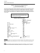
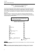
2. Secure the three brackets to the MODCELL 2050 using the pop-rivet gun, and 1/8" pop-rivets
supplied in conversion the kit (see Figure 1). All six rivets are inserted through the bracket and
into the housing.
3. Remove the QS-1300/1400 instrument from the Slide-Guide. Insert the MODCELL 2050 in
place of the old instrument. MODCELL 2050 should latch in place like the QS-1300/1400
instrument did.
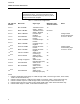
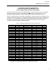
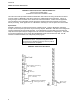
4. Connect wiring. When using kit number 2050FZ00000A, field I/O wiring for MODCELL 2050 may
be accomplished by cutting off the QS-1300 instrument connector and wiring directly to the
MODCELL 2050 termination block. See Table 1 for most common I/O configurations.
Figure 1. Mounting 2050R in Slide Guide