MODBUS Communications for MODCELL 2050R Indicating Process Controller 2050R Model B Version 2.8 2051R Model B Version 2.
MicroMod Automation, Inc. The Company MicroMod Automation is dedicated to improving customer efficiency by providing the most cost-effective, applicationspecific process solutions available. We are a highly responsive, application-focused company with years of expertise in control systems design and implementation. We are committed to teamwork, high quality manufacturing, advanced technology and unrivaled service and support.
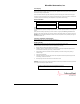
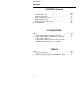
IB-23C650M CONTENTS CONTENTS Introduction . . . . . . . . . . . . . . . . . . . . . . . . . . . . . . . . . About This Supplement . . . . . . . . . . . . . . . . . . . . . . About Modbus Communications . . . . . . . . . . . . . . . . Installation . . . . . . . . . . . . . . . . . . . . . . . . . . . . . . . . . . Controller Option Requirements . . . . . . . . . . . . . . . . 2-Wire Modbus Network Connections . . . . . . . . . . . . 4-Wire Modbus Network Connections . . . . . . . . . . . .
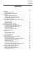
IB-23C650M CONTENTS CONTENTS (Cont’d) Totalizer Data (coils) ........................ Autotune Data (coils) . . . . . . . . . . . . . . . . . . . . . . . . Process Alarm Data (coils) . . . . . . . . . . . . . . . . . . . . Diagnostic Data (coils) . . . . . . . . . . . . . . . . . . . . . . . Ramp/Soak Profile Data (coils) . . . . . . . . . . . . . . . . . Record of Database . . . . . . . . . . . . . . . . . . . . . . . . . . . .
IB-23C650M INTRODUCTION INTRODUCTION About This Supplement This supplement provides instructions for installation, setup, and use of the Modbus RS-485 serial communications option available in the MODCELL 2050 Single Loop Controller. Comprehensive instructions covering all aspects of the controller not related to Modbus communication are included in the IB-23C650 User’s Guide.
IB-23C650M INTRODUCTION allows it to be identified by the master. This permits multiple slaves (controllers) to reside on a single Modbus network. The controller can be assigned any address between 1 and 247. Addresses are set in the RS-485 MENU as part of the setup for modbus communication. Address 0 is the “broadcast” address. Only write messages can use it. All controllers process the message, but there is no response back to the host. Other types of slaves may reside on a network with the controllers.
IB-23C650M INSTALLATION INSTALLATION This section provides instructions for making Modbus network connections using either a 2-wire or 4-wire configuration. This information assumes that physical installation and all other electrical connections are being made in accordance with the instructions in IB-23C650. Before making any connections, be sure the controller can support Modbus communications; see the option requirements below.
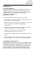
IB-23C650M INSTALLATION Personal Computer Modbus Master All resistors are 0.25W. RS485 Interface Other 2050R's wired same way without resistors. +5V dc 560 560 RX/TX+ RX/TX- 120 120 COM RX+ RX TX+ TX - COM Figure 1. Typical 2-Wire Modbus Network Connections.
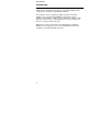
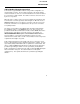
IB-23C650M INSTALLATION 4-Wire Modbus Network Connections Connections for typical Modbus networks using a 4-wire configuration are shown in Figures 2 and 3. The host device functions as the master and the controllers function as slaves. It is recommended that no more than 32 devices be connected on a single network. The number of devices can be increased by the use of repeaters. When the host is a device such as a personal computer, the instruments and host must have a common ground as shown in Figure 2.
IB-23C650M INSTALLATION Personal Computer Modbus Master All resistors are 0.25W. RS485 Interface Other 2050R's wired same way without resistors. +5V dc 560 RX+ 560 560 560 RX- 120 120 120 120 TX+ TXCOM 2050R Controller (Modbus Slave) RX+ RX TX+ TX - COM Last 2050R Figure 2.
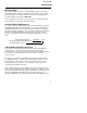
IB-23C650M INSTALLATION Modcell Processor All resistors are 0.25W. Isolated +5Vdc 560 TERM Switch YES Other 2050R's wired same way without resistors. S31 1 2 RX+ RX- 120 120 120 120 S32 1 2 TX+ TX- Modbus Master 2034N RS-485 MODULE (Module Locations 31 & 32) 2050R Controller (Modbus Slave) RX+ RX TX+ TX - COM Last 2050R Figure 3.
IB-23C650M INSTALLATION Blank Page 8
IB-23C650M COMMUNICATION APPLICATIONS COMMUNICATION APPLICATIONS The following are sample applications available with the controller through the use of Modbus communications. The RS-485 MENU is used to set up the controller for these applications. The setup requirements are described in detail in Table 1.
IB-23C650M COMMUNICATION APPPLICATIONS Attributes in the RS-485 MENU permit the supervisory control mode to be indicated via the set-point status display on the front of the instrument. Each of the three characters in the status display is configurable so that the user can choose an appropriate mnemonic to represent the supervisory control mode. A timeout value can be defined for communications traffic to the instrument via the Computer Timeout attribute.
IB-23C650M RS-485 COMMUNICATIONS SETUP RS-485 COMMUNICATIONS SETUP Before starting the communications setup, refer to the Setup Section in IB-23C650 for information about the setup preparation, method, and controls. Perform the communications setup using the RS-485 MENU as described in Table 1. Note: In order to access the RS-485 MENU, the RS-485 Communications Enable attribute in the BASE CONFIGURATION MENU must be set at YES. Refer to Table 1, Base Configuration in IB-23C650.
IB-23C650M RS-485 COMMUNICATIONS SETUP Table 1. RS-485 Setup Menu Step Step Description Top Display 1 RS-485 Menu. (requires option board) UP moves to RELAYS **MENU**. DN moves to RAT BIAS **MENU** if A/M ratio bias is enabled, or to SETPTS **MENU** otherwise. SCRL advances to Step 2 (read only in auto). 2 Bus Enable UP or DN selects ON or OFF. SCRL to advance to Step 3. BUS 3 Instrument Address UP or DN sets instrument address. SCRL to advance to Step 4.
IB-23C650M RS-485 COMMUNICATIONS SETUP Table 1. RS-485 Setup Menu Middle Display **MENU** ENABLE Bottom Display Entry Description None. ON = enables the bus for communications with a host device. OFF = disables the communications bus from receiving or writing with a host device. The bus must be disabled in order to make changes in the following steps. ADDRESS XXX Where X is any address between 1 and 247. Each instrument on a bus must have a unique address.
IB-23C650M RS-485 COMMUNICATIONS SETUP Table 1. RS-485 Setup Menu Step Step Description Top Display 8 Computer Activity Setup. UP begins setup at Step 8.1. SCRL to advance to Step 9 (Enable Bus). COMPUTER 8.1 Computer Activity Timeout. UP or DN sets value. SCRL to advance to Step 8.2. COMPUTER 8.2 Computer Activity Mnemonic (Auto ) UP or DN sets value (press UP to begin then press UP to start at A or press DN to start at 9 ). Press SCRL to access the next character.
IB-23C650M RS-485 COMMUNICATIONS SETUP Table 1. RS-485 Setup Menu Middle Display SETUP TIMEOUT Bottom Display Entry Description Steps 8.1 through 8.12.6.1.1allow setup for the controller to be used as a computer auto/manual (CAM) or supervisory station when connected to a host device. No entries are required if the instrument is to be used as a stand alone controller which can receive read/write commands from a host device. XXXXX X represents a time between 1 and 16383 seconds.
IB-23C650M RS-485 COMMUNICATIONS SETUP Table 1. RS-485 Setup Menu Step Step Description Top Display 8.4. Computer Control Mode Value UP or DN sets value. SCRL to advance to Step 8.5 8.5 Computer Set-point Mnemonic (Local) UP or DN sets value (press UP to begin then press UP to start at A or press DN to start at 9. Press SCRL to access the next character. Repeat through the third character. Press SCRL after the third character to continue with Step 8.6. CMP LOC 8.
IB-23C650M RS-485 COMMUNICATIONS SETUP Table 1. RS-485 Setup Menu Middle Display MODE VAL Bottom Display Entry Description XXX Where X = any value between 0 and 255. This value is OR'd into bits 9-12 of the Control Mode register (#14) when the activity timer is enabled. Default value is 1.
IB-23C650M RS-485 COMMUNICATIONS SETUP Table 1. RS-485 Setup Menu Step Step Description Top Display 8.8 Computer Set-point Mnemonic (Local 4) UP or DN set values and SCRL accesses characters as described in Step 8.5. Press SCRL after the third character to continue with Step 8.9. CMP LO4 8.9 Computer Set-point Mnemonic (Remote) UP or DN set values and SCRL accesses characters as described in Step 8.5. Press SCRL after the third character to continue with Step 8.10. CMP REM 8.
IB-23C650M RS-485 COMMUNICATIONS SETUP Table 1. RS-485 Setup Menu Middle Display MNEMONIC Bottom Display Entry Description XXX Where X = any of the characters listed in Step 8.5. Mnemonic appears in the set-point status display when the activity timer is initialized by the host and set-point source is Local 4. Default is LO4. MNEMONIC XXX Where X = any of the characters listed in Step 8.5.
IB-23C650M RS-485 COMMUNICATIONS SETUP Table 1. RS-485 Setup Menu Step Step Description Top Display 8.12.1 Computer Fail Control Mode. UP or DN sets desired mode. SCRL to advance to Step 8.12.2 from AUTO if output 2 is available Step 8.12.3 from AUTO if Relay A is available Step 8.12.4 from AUTO if Relay B is available Step 8.12.5 from AUTO if Relay C is available or to Step 8.12.1.1 otherwise. CMP FAIL 8.12.1.1 Computer Fail Output. UP or DN sets control output value. SCRL to advance to Step 8.12.
IB-23C650M RS-485 COMMUNICATIONS SETUP Table 1. RS-485 Setup Menu Middle Display CTL MODE Bottom Display Entry Description LAST =controller maintains the same control mode after a communications failure has been detected. MANUAL =controller operates in manual following a computer failure with the output as defined in Step 8.12.1.1. AUTO =controller operates in automatic following a computer failure with the set-point as defined in Step 8.12.6.1.1.
IB-23C650M RS-485 COMMUNICATIONS SETUP Table 1. RS-485 Setup Menu Step Step Description Top Display 8.12.2.1 Computer Fail Output 2 Value. UP or DN sets output 2 value. SCRL to advance to any step between 8.12.3 and 8.12.5 for additional outputs enabled as manual or computer only. If no outputs are assigned to manual or computer only, continue with Step 8.12.6 (Computer Fail Set-point Mode). CMP FAIL 8.12.3 Computer Fail Relay A. UP or DN sets relay condition. SCRL to advance to Step 8.12.
IB-23C650M RS-485 COMMUNICATIONS SETUP Table 1. RS-485 Setup Menu Middle Display OUT2 VAL Bottom Display Entry Description XXX Where X = any value between 0 and 100%. This is the output 2 value the controller will have if the retransmission variable in the "MA OUTP MENU" has been selected as manual or computer only and a computer failure has been detected. RELAY A LAST =relay state remains as it was prior to the detection of a computer fail. OFF =relay goes to off state after a computer fail.
IB-23C650M RS-485 COMMUNICATIONS SETUP Table 1. RS-485 Setup Menu Step 8.12.6.1 Step Description Computer Fail Set-point UP or DN sets the set-point value. SCRL to advance to step 9 (Bus Enable) from LAST or Step 8.12.6.1.1 (Computer Fail Set-point Value) from NEW VALU. 8.12.6.1.1 Computer Fail Set-point Value. Top Display CMP FAIL CMP FAIL UP or DN sets the set-point value. SCRL to advance to Step 9 (Bus Enable) 9 24 Bus Enable. UP or DN selects ON or OFF.
IB-23C650M RS-485 COMMUNICATIONS SETUP Table 1. RS-485 Setup Menu Middle Display Bottom Display SETPOINT LAST If any of the LOCAL set-point sources were NEW VALU selected in the previous step, "LAST" will Entry Description cause the controller to use the current set-point value in that location. Selecting "NEW VALU" allows a new value (defined in Step 8.12.6.1.1) to be written into the set-point source register.
IB-23C650M RS-485 COMMUNICATIONS SETUP Blank Page 26
IB-23C650M BASIC OPERATION WITH A HOST DEVICE BASIC OPERATION WITH A HOST DEVICE This section supplements the Basic Operation Section in IB-23C650. It covers the operational activities related to Modbus communication which are performed in the DISPLAYS MENU. Enabling Write Communication With a Host After completing the RS-485 communications setup, the host can read instrument data when the bus is enabled (see Table 1, Step 9).
IB-23C650M BASIC OPERATION WITH A HOST DEVICE If necessary, the operator can disable the host from writing to the controller. This gives the operator total control of the instrument operation. The host can still read data from the instrument but cannot write to it. To disable the host, access the CMP status display as described in the previous section. When CMP appears, press the DN or UP key to change the status from ENABLED to LOCKED.
IB-23C650M BASIC OPERATION WITH A HOST DEVICE Supervisory Station When the controller and host device are configured to provide a supervisory function, the controller receives its set-point from the host device. The controller executes its PID algorithm in the normal manner, and in general functions the same as a standard controller. This activity is initiated by the host.
IB-23C650M BASIC OPERATION WITH A HOST DEVICE Computer Auto/Manual Station When the controller and host device are configured to provide a computer auto/manual function, the host performs the PID control function. The results are communicated to the instrument and then to the field. This activity is initiated by the host. The displays and control key operation for a computer auto/manual station are as follows: Tag display can be configured to indicate that the host has initiated activity.
IB-23C650M BASIC OPERATION WITH A HOST DEVICE Diagnostic Messages The controller provides diagnostic messages which alert the user to communication problems . The Diagnostic messages are displayed on the TAG line. When one or more unacknowledged messages exist, the red LED on the ALARM key flashes, the message alternates with the TAG on the top display, and the beeper sounds if configured to do so. This activity continues until all diagnostic conditions are either acknowledged or no longer active.
IB-23C650M BASIC OPERATION WITH A HOST DEVICE 32
IB-23C650M MODBUS PROTOCOL MODBUS PROTOCOL Communications Speed The controller supports baud rates of 150, 300, 1200, 2400, 4800, 9600, 19.2K, and 38.4K baud. Messages are not buffered. A new message (including broadcast type) will not be accepted until an existing message has been processed and responded to if necessary. Message Response Time The controller typically takes between 10 and 30 milliseconds to respond to a message requesting 10 registers.
IB-23C650M MODBUS PROTOCOL Messages Supported The controller utilizes registers and coils to access information. The following MODBUS messages are supported by the controller. See the Gould MODBUS Protocol Reference Guide dated Jan. 1985 for further detail. Note: 34 In cases where the controller processor is already heavily loaded, it may be necessary to limit the number of registers or coils addressed by any single message.
IB-23C650M MODBUS PROTOCOL Table 2. MODBUS messages supported by the 2050R Controller MODBUS MODBUS Function Message Name Code 2050R Definition 01 Read Coil Status Read "n" consecutive discrete (boolean) points from a specified starting point. The controller returns zeros for points which do not contain defined data and will nak any request for point numbers greater than 9999. See Note, page 34. 02 Read Input Status Same as Read Coil Status.
IB-23C650M MODBUS PROTOCOL Message Formats The following message formats are used to transfer information between the controller and a host. Refer to the message format example for format details. Read Coil Status, Read Input Status Master Message Format Bytes 0 1 2&3 Device Address Function Code 4&5 Starting Coil Number 6&7 Number of Coils CRC Slave Response Bytes 0 Device Address 1 2 Function Code 3 Number of Data Bytes Data byte #1 ... x ...
IB-23C650M MODBUS PROTOCOL Preset Single Register Master Message Format Bytes 0 1 Device Address Function Code 2&3 Register Number 4&5 6&7 Register Data CRC Slave Response (simple echo) Bytes 0 1 Device Address Function Code 2&3 Register Number 4&5 6&7 Register Data CRC Loopback Diagnostic Test Master Message Format Bytes 0 1 Device Address Function Code 2&3 Diagnostic Code (0000 only) 4&5 6&7 Data (ignored) CRC Slave Response (simple echo) Bytes 0 1 Device Address Function Code
IB-23C650M MODBUS PROTOCOL Preset Multiple Registers Master Message Format Bytes 0 1 Device Address Function Code 2&3 4&5 Starting Register Number 6 Number Number of of Data Registers Bytes ... 7&8 Register Data 1 x& x+1 x +2 & x+3 ... Register CRC Data n Slave Response Bytes 0 1 2&3 Device Address Function Code 4&5 6&7 Starting Register Number Number of Registers CRC Coil Data Example Coil data is packed 1 bit per coil.
IB-23C650M CONTROLLER ATTRIBUTE LISTING - REGISTER DATA CONTROLLER ATTRIBUTE LISTING - REGISTER DATA The tables in this section provide a listing of the controller’s numeric attributes which are addressed as registers. The tables divide the attributes into related groups such as tuning, alarms, etc. A group of numeric attributes may have associated boolean (discrete) attributes which are addressed as coils. The boolean attributes are listed in the next section.
IB-23C650M CONTROLLER ATTRIBUTE LISTING - REGISTER DATA Common Data (registers) Cont’d Reg. # 7 R_ 8 Description Field Input 1 Register #9, Bits 1 & 0 = 0 Register #9, Bits 1 & 0= 1 Register #9, Bits 1 & 0= 2 Register.#9, Bits 1 & 0 = 3 Note: This register permits reading of actual process input to 2050R when Coil #14 is TRUE. Data is copied to Reg. #10 when Coil #14 is FALSE. Field Input 2 Register Value -32000 to +32000 -32000 to +32000 -32000 to +32000 -32000 to +32000 Same as Reg.
IB-23C650M CONTROLLER ATTRIBUTE LISTING - REGISTER DATA Common Data (registers) Cont’d Reg. # 14 Bits 9-2 RW Bit 10 RW Bit 1 RW Bit 0 RW 15 Bits 13 - 6 RW Bits 5-0 RW Description Computer active control mode value (this is a copy of register #77). This part present only when activity timer is enabled. Output Tracking Computer Auto/Manual status. When Coil #10 is TRUE, the A and M keys change this status instead of the controller mode. This part present only when activity timer is enabled.
IB-23C650M CONTROLLER ATTRIBUTE LISTING - REGISTER DATA Ramp/Soak Profile and Totalizer Data (registers) Description Register Value 2050R Displayed Value 30 R_ Ramp/soak segment time remaining. Time remaining in the currently active ramp/soak segment. 0 to 32000 0.0 to 3200 31 R_ Current ramp/soak cycle. 0 to 65535 0 to 65535 32 R_ Current ramp/soak segment 1 to 10 1 to 10 33 R_ Floating point totalized count hi bytes. Upper 2 bytes of totalized count in IEEE floating point format. Reg.
IB-23C650M CONTROLLER ATTRIBUTE LISTING - REGISTER DATA Ramp/Soak Profile and Totalizer Data (registers) Cont’d Reg. # Description 39 Floating point totalizer predetermined R W count hi bytes. Upper 2 bytes of totalizer predetermined count in IEEE floating point format. 40 Floating point totalizer predetermined R W count low bytes. Lower 2 bytes of predetermined count in IEEE floating point format 41 Integer totalizer predetermined count.
IB-23C650M CONTROLLER ATTRIBUTE LISTING - REGISTER DATA Tuning Parameter Data (registers) Reg. # Description 50 Autotune output step size RW 51 Autotune hysteresis value RW Register No. 9 = 0 Register No. 9 = 1 Register No. 9 = 2 Register No. 9 = 3 52 Autotune process variable maximum R W (high trip point) Register #9, bits 1 & 0 = 0 44 2050R Displayed Value 1 TO 500 0.1 to 50.0 1 to 30000 1 to 30000 1 to 30000 1 to 30000 0.1 to 3000.0 0.01 to 300.00 0.001 to 30.000 0.001 to 30.000 -29970 or Reg.
IB-23C650M CONTROLLER ATTRIBUTE LISTING - REGISTER DATA Tuning Parameter Data (registers) Cont’d Register Value 2050R Displayed Value 55 Gain or heat gain value RW 1 to 30000 0.1 to 3000.0 56 Reset or heat reset RW 10 to 12000 0.01 to 120.00 repeats/minute 57 Preact value RW 0 to 30000 0.0 to 3000.0 seconds derivative response Reg. # Description 58 Manual reset value RW 0 to 1000 0.0 to 100.0% -30000 to 30000 -300.00to 300.
IB-23C650M CONTROLLER ATTRIBUTE LISTING - REGISTER DATA Alarm Data (registers) Reg. # Register Value 2050R Displayed Value -2995 to 30000 -2995 to 30000 -2995 to 30000 -2995 to 30000 -2995 to 30000 -299.5 to 3000.0 -29.95 to 300.00 -2.995 to 30.000 • Deviation High or Low Register #9, bits 1 & 0 = 0 Register #9, bits 1 & 0 = 1 Register #9, bits 1 & 0 = 2 Register #9, bits 1 & 0 = 3 1 to 30000 1 to 30000 1 to 30000 1 to 30000 1 to 30000 0.1 to 3000.0 0.01 to 300.00 0.001 to 30.
IB-23C650M CONTROLLER ATTRIBUTE LISTING - REGISTER DATA Computer Activity Data (registers) Reg. # Description 74 Computer active: timeout value RW Register Value 2050R Displayed Value 1 to 16383 1 to 16383 sec. 75 Automatic control mode status display ASCII code for first R W mnemonic with computer active. character in status Default display is CMP. Each display character is configurable; this register defines the first character (C in the default CMP).
IB-23C650M CONTROLLER ATTRIBUTE LISTING - REGISTER DATA Computer Activity Data (registers) Cont’d Register Value 2050R Displayed Value 0 to 255 0 to 255 81 Computer fail: control mode RW 0 1 2 Last Manual Auto 82 Computer fail: output value RW 0 to 1000 0.0 to 100.0% 83 Computer fail: output 2 value RW 0 to 1000 0.0 to 100.0% 0 1 2 Last Off On Reg. # Description 80 Computer active: set-point mode value RW 84 Computer fail: relay A RW 85 Computer fail, relay B RW Same as Reg.
IB-23C650M CONTROLLER ATTRIBUTE LISTING - REGISTER DATA Ramp/Soak Profile Configuration Data (registers) Reg. # Description 89 Ramp/soak soak hysteresis RW Register #9, bits 1 & 0 = 0 Register #9, bits 1 & 0 = 1 Register #9, bits 1 & 0 = 2 Register #9, bits 1 & 0 = 3 90 Ramp/soak ramp hysteresis RW 91 Ramp/soak number of segments RW Register Value 2050R Displayed Value 1 to 30000 1 to 30000 1 to 30000 1 to 30000 Same as Reg. #89 1 to 30000 0.1 to 3000.0 0.01 to 300.00 0.001 to 30.000 Same as Reg.
IB-23C650M CONTROLLER ATTRIBUTE LISTING - REGISTER DATA Ramp/Soak Profile Configuration Data (registers) Cont’d Reg. # Register Value 2050R Displayed Value 99 Ramp/soak segment 4 ending setR W point Same as Reg. #93 Same as Reg. #93 100 Ramp/soak segment 4 ramp-rate or R W soak-time Same as Reg. #94 Same as Reg. #94 101 Ramp/soak segment 5 ending setR W point Same as Reg. #93 Same as Reg. #93 102 Ramp/soak segment 5 ramp-rate or R W soak-time Same as Reg. #94 Same as Reg.
IB-23C650M CONTROLLER ATTRIBUTE LISTING - REGISTER DATA More Computer Activity Data (registers) Reg. # Description Register Value 2050R Displayed Value 113 Manual control mode status display ASCII code for first R W mnemonic with computer active. character in status Default display is MAN. Each display character is configurable; this register defines the first character (M in the default MAN). Letter M (default) or letters A-Z, numbers 0-9 plus other special characters per configuration.
IB-23C650M CONTROLLER ATTRIBUTE LISTING - REGISTER DATA More Computer Activity Data (registers) Cont’d Reg. # Description Register Value 2050R Displayed Value 119 Local 4 set-point status display Same as Reg. #113 R W mnemonic with computer active. Default display is LO4. Each character is configurable; this register defines the first character (L in the default LO4). Letter L (default) or other configured character. See Reg. #113. 120 Same as display described in Reg. Same as Reg. #114 R W #119.
IB-23C650M CONTROLLER ATTRIBUTE LISTING - REGISTER DATA More Computer Activity Data (registers) Cont’d Reg. # Description Register Value 2050R Displayed Value 127 Same as display described in Reg. Same as Reg #124 R W #124. This register defines the seventh and eighth characters (E and R in the default COMPUTER Letters E and R (default)or other configured characters. See Reg. #114. 128 Loop Tag Display.
IB-23C650M CONTROLLER ATTRIBUTE LISTING - REGISTER DATA Blank Page 54
IB-23C650M CONTROLLER ATTRIBUTE LISTING - COIL DATA CONTROLLER ATTRIBUTE LISTING - COIL DATA The tables in this section provide a listing of the 2050R boolean (discrete) attributes which are addressed as coils. The description column identifies the TRUE state of each attribute. The binary values are: • TRUE = 1 • FALSE = 0 The tables list the attributes in order by Modbus coil number.
IB-23C650M CONTROLLER ATTRIBUTE LISTING - COIL DATA Computer Activity Data (coils) Cont’d Coil. # Description Reference Information 14 Decouple field input 1 from process R W variable. 15 Decouple field input 2 from internal R W variable. 16 Computer active RW Write to start computer activity timer; Read to see if timer is running (see Table 1, Step 8.1). 17 Computer writes enabled RW See Standard Communication With a Host in the Basic Operation With A Host Device Section of this supplement.
IB-23C650M CONTROLLER ATTRIBUTE LISTING - COIL DATA Ramp/Soak Data (coils) 25 Ramp/soak RUN RW See Ramp/Soak Operation in the IB-23C650 User’s Guide. 26 _W Ramp/soak RESET Same as Coil #25 27 _W Ramp/soak SKIP Same as Coil #25 Totalizer Data (coils) Coil # Description 28 Totalizer RUN RW 29 _W Reference Information See Totalizer Operation in the IB-23C650 User’s guide.
IB-23C650M CONTROLLER ATTRIBUTE LISTING - COIL DATA Process Alarm Data (Coils) 41 R_ Process alarm 1 active (Reg. # 9, PA1) 42 Process alarm 1 unacknowledged R W (Reg. # 6, PA1) 43 R_ Process alarm 2 active (Reg. # 9, PA2) See Control Keys in the Basic Operation Section of the IB23C650 User’s Guide. Write to acknowledge process alarm from computer. Same as coil #41 44 Process alarm 2 unacknowledged R W (Reg. # 6, PA2) Same as coil #42 45 R_ Same as coil #41 Process alarm 3 active (Reg.
IB-23C650M CONTROLLER ATTRIBUTE LISTING - COIL DATA Diagnostic Data (coils) Coil # 49 R_ Description Process fault diagnostic active (Reg. # 9, DIAG1) 50 Process fault diagnostic unacknowledged R W (Reg. # 6, DIAG1) 51 R_ Input 2 fault diagnostic active (Reg. # 9, DIAG2) Reference Information See Operational Failure Messages in the Diagnostics Section of the IB-23C650 User’s Guide. Write to acknowledge diagnostic from computer. Same as Coil #49 52 Input 2 fault diagnostic unacknowledged R W (Reg.
IB-23C650M CONTROLLER ATTRIBUTE LISTING - COIL DATA Ramp/Soak Profile Data (coils) 73 Ramp soak repeat RW See Table 9, Ramp/Soak Profile Setup Menu in the IB-23C650 User‘s Guide.
IB-23C650M CONTROLLER ATTRIBUTE LISTING - COIL DATA Ramp/Soak Profile Data (coils) Cont’d Coil. # Description 91 Ramp soak segment 5 relay A state on RW Reference Information See Table 9, Ramp/Soak Profile Setup Menu in the IB-23C650 User‘s Guide.
IB-23C650M CONTROLLER ATTRIBUTE LISTING - COIL DATA Ramp/Soak Profile Data (coils) Cont’d Reg. # Description Reference Information 106 Ramp soak segment 8 guaranteed Ramp or See Table 9, Ramp/Soak Profile R W Soak Setup Menu in the IB-23C650 User‘s Guide.
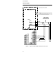
IB-23C650M CONTROLLER ATTRIBUTE LISTING - COIL DATA RECORD OF DATABASE DESCRIPTION This section provides a table of the database fields for planning and recording your configuration entries via the RS-485 configuration menu. This database record provides a reference when entering the configuration and then a record of your configuration. Make copies of these pages as needed. Blank fill-in fields on this table represents configuration fields that require a selection.
IB-23C650M CONTROLLER ATTRIBUTE LISTING - COIL DATA Top Display Bot. Disp. Entry Top Display Middle Display aaaaaaaaaa aaaaaaaaaa aaaaaaaaaa aaaaaaaaaa aaaaaaaaaa aaaaaaaaaa aaaaaaaaaa aaaaaaaaaa Data Base Record Middle Display Bot. Disp.
The Company’s policy is one of continuous product improvement and the right is reserved to modify the information contained herein without notice, or to make engineering refinements that may not be reflected in this bulletin. Micromod Automation assumes no responsibility for errors that may appear in this manual. © 2004 MicroMod Automation, Inc. Printed in USA IB-23C650M, Issue 2 9/2004 MicroMod Automation, Inc. 75 Town Centre Drive Rochester, NY USA 14623 Tel. 585-321 9250 Fax 585-321 9251 www.