
User Manual

IB-23C650M
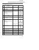
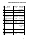
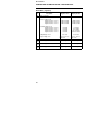
CONTROLLER ATTRIBUTE LISTING - REGISTER DATA
Common Data (registers) Cont’d
Reg.
#
Description Register Value
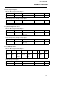
2050R
Displayed Value
14
Bits
9 - 2
R W
Computer active control mode value
(this is a copy of register #77).
This part present only when activity
timer is enabled.
0 to 255 Not Displayed
See RS-485 Setup;
Table 1, Step 8.4.
Bit 10
R W
Output Tracking 1
0
TRK
Bit 1
R W
Computer Auto/Manual status.
When Coil #10 is TRUE, the A and M
keys change this status instead of the
controller mode.
This part present only when activity
timer is enabled.
1
0
AUT
MAN
Displayed Mnemonic
is configurable,
defaults are shown.
See Reg. #75, 76,
113 & 114
Bit 0
R W
Control mode of 2050R 1
0
AUT
MAN
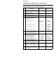
15
Bits
13 - 6
R W
Computer (host) Set-point mode value
This part present only when activity
timer is enabled.
5 to 255 Not Displayed
See RS-485 Setup;
Table 1, Step 8.10.
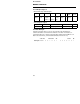
Bits
5 - 0
R W
Computer Remote/Local status.
When Coil #8 is TRUE, the R/L key
changes this status instead of the set-
point status.
This part present only when activity
timer is enabled.
0
1
2
3
4
•
•
•
to value in register
#123
LOC
LO2
LO3
LO4
REM
Displayed Mnemonic
is configurable for
values 0-5, defaults
are shown.
See Reg #78 &
#115 thru #122
Bits
2 - 0
R W
2050R Set-point source 0
1
2
3
4
LOC
LO2
LO3
LO4
REM
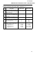
16
R W
Analog output #2 value -100 to 1100 -10.0 to 110.0
17
R W
Local set-point 1 value Same as Reg.#11 Same as Reg.#11
18
R W
Local set-point 2 value Same as Reg.#11 Same as Reg.#11
19
R W
Local set-point 3 value Same as Reg.#11 Same as Reg.#11
20
R W
Local set-point 4 value Same as Reg.#11 Same as Reg.#11
41