MODCELL™ Multiloop Processor Product Description, Installation and Wiring for 2002N Model C and Associated Hardware Installation
MicroMod Automation, Inc. The Company MicroMod Automation is dedicated to improving customer efficiency by providing the most cost-effective, application-specific process solutions available. We are a highly responsive, application-focused company with years of expertise in control systems design and implementation. We are committed to teamwork, high quality manufacturing, advanced technology and unrivaled service and support.
MODCELL Multiloop Processor CONTENTS CONTENTS Page 1 - PRODUCT DESCRIPTION 1.1 1.2 1.3 1.4 1.5 1.6 OVERVIEW . . . . . . . . . . . . . . . . . . . . . . . . . . . . . . . . . . . . . . . . . . . . . . . . . . . . . . . 1 EXPLANATION OF SERIAL AND CATALOG NUMBERS . . . . . . . . . . . . . . . . . . . . . . . 2 BASIC HARDWARE . . . . . . . . . . . . . . . . . . . . . . . . . . . . . . . . . . . . . . . . . . . . . . . . . 3 1.3.1 2002N MODCELL Multiloop Processor.- Flush Mount . . . . . . . . . . . . . .
MODCELL Multiloop Processor CONTENTS CONTENTS (Cont’d) 3.5 3.6 3.7 Page 3.4.2 Shield Ground . . . . . . . . . . . . . . . . . . . . . . . . . . . . . . . . . . . . . . . . . . . . . 26 3.4.3 Circuit Common Interconnection . . . . . . . . . . . . . . . . . . . . . . . . . . . . . . . . . 26 3.4.4 Electrical Noise . . . . . . . . . . . . . . . . . . . . . . . . . . . . . . . . . . . . . . . . . . . . . 26 3.4.5 Noise Prevention Measures . . . . . . . . . . . . . . . . . . . . . . . . . . . . . . . . . .
MODCELL Multiloop Processor CONTENTS ILLUSTRATIONS Page 1 2 21 1-1 1-2 2-1 Modcell 2002N Processor . . . . . . . . . . . . . . . . . . . . . . . . . . . . . . . . . . . . . . . . . . . . . . . Component Location, 2002N Processor . . . . . . . . . . . . . . . . . . . . . . . . . . . . . . . . . . . Mounting Dimensions, 2002N Processor - Flush Mount . . . . . . . . . . . . . . . . . . . . . . .. 3-1 3-2 3-3 3-4 3-5 3-6 3-7 3-8 3-9 3-10 3-11 3-12 3-13 3-14 Terminations for 2002N . . . . . . . . . . . . .
MODCELL Multiloop Processor CONTENTS iv
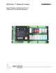
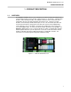
MODCELL Multiloop Processor PRODUCT DESCRIPTION 1 - PRODUCT DESCRIPTION 1.1 OVERVIEW The MODCELL Multiloop Processor is a microprocessor-based control unit comprised of a control identity module, memory module, single point process I/O modules, communication modules, and a termination facility. The modular architecture of the control unit can be configured to meet specific data acquisition and control needs.
MODCELL Multiloop Processor PRODUCT DESCRIPTION The 2002N Processor is packaged into a flush mount form for rack or panel mounting as shown in Figure 1-2. Figure 1-2. Component Location, 2002N Processor 1.2 EXPLANATION OF SERIAL AND CATALOG NUMBER The products described in this book have numbers that help identify specific features. In addition, some products are assigned a serial number which can be used to track manufacturing data. The general format of the catalog number is described below.
MODCELL Multiloop Processor PRODUCT DESCRIPTION 1.3 BASIC HARDWARE The descriptions included in this section give a brief overview of the functions and features of the basic hardware. 1.3.1 2002N MODCELL Multiloop Processor - Flush Mount The instrument CPU is based on the 16 MHZ 68302 microprocessor. An identity module (2001P) provides the functionality that gives the instrument the capability to execute a user-configured database.
MODCELL Multiloop Processor PRODUCT DESCRIPTION 1.3.3 2001P Logic Control Identity Module The identity module gives the processor a specific level of process and communications functionality. The logic control identity provides the capability to execute a user-configured database which consists of I/O module handling capabilities and a collection of basic elements called function blocks.
MODCELL Multiloop Processor PRODUCT DESCRIPTION 1.3.4 2004P Advanced Control Identity Module The identity module gives the processor a specific level of process and communications functionality. The advanced control identity provides the same capabilities as the logic and regulatory identity modules plus PID block functionality. Catalog Number Description for 2004P 1.3.
MODCELL Multiloop Processor PRODUCT DESCRIPTION 1.4 I/O MODULES The descriptions included in this section give a brief overview of the functions and features of the I/O modules. 1.4.1 2001A Voltage Input Module The voltage input module provides dual ranges of ±10V dc and ±100 mV dc selectable at configuration time. Input to the module is scaled and then applied to an integrating analog to digital converter.
MODCELL Multiloop Processor PRODUCT DESCRIPTION 1.4.2 2002A Current Input Module The current input module is identical to the voltage input module except for the addition of a 250 ohm resistor across the two input leads. This allows the standard 4-20 mA DC input range to be accommodated by the module. This module uses the Voltage/Current Input Module (VCIM) Block for configuration of input parameters.
MODCELL Multiloop Processor PRODUCT DESCRIPTION 1.4.4 2013A Thermocouple Input Module (with upscale burnout detection) The thermocouple input module is identical to the ±100 mV voltage input module except for the addition of upscale burnout detection circuitry. Thermocouple types allowed are: B, E, J, K, N, S, or T. A cold junction compensator (CJC) module is used to sense the temperature at the terminal block for all thermocouples.
MODCELL Multiloop Processor PRODUCT DESCRIPTION 1.4.6 2004A Solid-State Relay Input Module The Solid-State Relay Input module provides the necessary interfacing for AC or DC digital inputs when high isolation voltages are required (250V rms isolation limitation through termination panel). This module uses the Digital Input Module (DIM) Block for configuration of input parameters.
MODCELL Multiloop Processor PRODUCT DESCRIPTION 1.4.8 2006A Nonisolated Digital Input Module The Nonisolated Digital Input Module is primarily intended for instrument-to-instrument signaling. The module interfaces 24-volt on/off signals with no isolation or accepts switch contact closures without external power requirements. This module uses the Digital Input Module (DIM) Block for configuration of input parameters.
MODCELL Multiloop Processor PRODUCT DESCRIPTION 1.4.10 2011A Mechanical Relay Output Module The Mechanical Relay Output Module may have dual SPST relays or a Form C relay. This module uses the Dual Digital Output Module (DDOM) Block for configuration of dual SPST output parameters or the Wide Digital Output Module (WDOM) Block for configuration of Form C output parameters.
MODCELL Multiloop Processor PRODUCT DESCRIPTION 1.4.12 2020N Remote I/O Interface Module Remote Input and Output Modules expand the I/O capability of a MODCELL Multiloop Processor to a total of 150 discrete points. The modules communicate to the Multiloop Processor over the CS-31 Remote I/O Network, an RS-485 bus which connects the remote I/O base units to the 2020N Remote I/O plug-in module.
MODCELL Multiloop Processor PRODUCT DESCRIPTION 1.5.2 2032N RS-485 Communication Module for Modbus (2-Wire) This RS-485 Communication module is a 75LBC176D bidirectional transceiver that provides 2-wire Modbus communications capability for the processor. This module can be used for either a point-to-point or point-to-multipoint network. The Modbus communications supported by this module are used only for reading and writing controller attributes.
MODCELL Multiloop Processor PRODUCT DESCRIPTION 1.5.4 2034N RS-485 Communication Module for Modbus (4-Wire) This RS-485 Communication module is a pair of 75LBC176D transceivers that provides Extended Modbus communications capability for the processor. This module can be used for either a point-to-point or point-to-multipoint Modbus network.
MODCELL Multiloop Processor PRODUCT DESCRIPTION 1.6 RELATED DOCUMENTATION Reference information on the data base structure and configuration parameters for this instrument can be found in the following documents.
MODCELL Multiloop Processor PRODUCT DESCRIPTION 16
MODCELL Multiloop Processor MECHANICAL INSTALLATION 2 - MECHANICAL INSTALLATION 2.1 GENERAL Read these instructions thoroughly before starting installation. Installation personnel should be qualified technicians. Observe all electrical code requirements and safety standards during installation. Installing the controller involves: • Unpacking (Section 2.2) • Installing Modules (Section 2.3) • Mounting (Section 2.4) NOTE: As part of the installation, a fan must be installed as described in Section 2.
MODCELL Multiloop Processor MECHANICAL INSTALLATION Table 2-1.
MODCELL Multiloop Processor MECHANICAL INSTALLATION 2.3.2 Current Consumption The Model C multiloop processor has the capacity to handle any mix of I/O that uses 4.5 amps of current or less. Add the current consumption for each I/O module, using the planning form in Appendix A, and verify that the total does not exceed 4.5 amps.
MODCELL Multiloop Processor MECHANICAL INSTALLATION 2.4 MOUNTING The instrument must be installed in an approved enclosure or installed in a means acceptable to the authority having jurisdiction for electrical installations. WARNING Do not install a MODCELL Multiloop Processor in a residential, commercial or light industrial environment in the European Union. Select a mounting location where: 20 • There is minimum vibration.
MODCELL Multiloop Processor MECHANICAL INSTALLATION 2.4.1 2002N Multiloop Processor - Flush Mount The flush mount processor can be mounted directly in a rack or panel. Assure that electrical wire routing and and support are planned as required for each processor. Mount the processor as follows: 1. Mount the processor, Figure 2-5, in any available position in a rack or panel. Ensure that the mounting screws provide good metal to metal contact between the processor and its mounting surface.
MODCELL Multiloop Processor MECHANICAL INSTALLATION 22
MODCELL Multiloop Processor ELECTRICAL CONNECTIONS 3 - ELECTRICAL CONNECTIONS 3.1 TERMINAL IDENTIFICATION The power wiring connections and input/output (I/O) connections are made with the multiloop processor installed in its operating location. The view of the 2002N in Figure 3-1 shows the terminals available for inputs and outputs. 3.2 CONNECTION GUIDELINES The recommended wiring procedure is as follows: 1. On a copy of the wiring planning sheet, Appendix A, list each wire connection.
MODCELL Multiloop Processor ELECTRICAL CONNECTIONS Slot N / Slot N+1 2030FZ00002A ICN Terminator Red Pin = 24V Figure 3-1.
MODCELL Multiloop Processor ELECTRICAL CONNECTIONS 3.3 POWER CONNECTIONS WARNING Avoid electrical shock. AC power wiring must not be connected at the distribution panel (ac source) until all wiring procedures are completed. All power wiring must be in compliance with the requirements of the National Electrical Code or Canadian Electrical Code.
MODCELL Multiloop Processor ELECTRICAL CONNECTIONS 3.4.2 Shield Ground The shield terminals, Figure 3-1, are only connected to one another; they are not internally connected to chassis ground or circuit common. Two brass jumper straps are included with each processor to connect chassis ground and/or circuit common to the shield terminals. Failure to make these connections renders all shield connections useless. When installing the jumpers consider the following: 3.4.
MODCELL Multiloop Processor ELECTRICAL CONNECTIONS 3.4.5 Noise Prevention Measures Primary power circuit distribution system: • Ideally, each microprocessor-based device should be provided with an independent dedicated power source. Where this approach is not feasible due to space available or cost per device an acceptable alternative is to install constant voltage, isolation transformers in the branch circuit where the microprocessor-based device is installed.
MODCELL Multiloop Processor ELECTRICAL CONNECTIONS 3.5 • Any connection made to provide a noise ground should be kept as short as possible using the largest practical wire gauge. This is necessary to keep the inductance of the connection as low as possible. Bear in mind that noise spikes have very short rise times and that any inductance will appear as a high impedance.
MODCELL Multiloop Processor ELECTRICAL CONNECTIONS LOWER TERMINAL HOUSING BASE INSTRUMENT 2013A TC INPUT MODULE (Module Location 17) Upscale Burnout Detection Thermocouple (B,E,J,K,N,R,S,T) +V 3 6 +5V DATA SH2 4 7 SEL CLK A 5 GND +10V Iso S17 1 1 2 A/D 2 Input Isolation Processor Red (-) Shield Connection to Either Terminal B Figure 3- 2. Typical Input Circuit for 2013A Thermocouple Input Module Table 3-1.
MODCELL Multiloop Processor ELECTRICAL CONNECTIONS 3.5.2 2004A SSR Input (DIM) Make Solid-State Relay (SSR) connections as shown in Figure 3-4. These input modules are used for sensing ON/OFF voltage levels. Each module provides optical isolation between the field devices and the control logic. This isolation is limited to 250 Vrms at the terminal block.
MODCELL Multiloop Processor ELECTRICAL CONNECTIONS UPPER TERMINAL HOUSING 2004A _ _ _ 10, 11 _ SOLID STATE RELAY INPUT MODULE (Module Location 10) 3 S10 + DC Power Supply BASE INSTRUMENT 1 1 4 OR 5 2 – +5V To Microprocessor 2 2004A _ _ _ 12, 13, 14, 15 _ SOLID STATE RELAY INPUT MODULE (Module Location 11) S11 L1 or + AC/DC Power Supply 1 1 2 2 3 +5V 4 To Microprocessor OR L2 or – 5 S-3031-16 Figure 3- 3.
MODCELL Multiloop Processor ELECTRICAL CONNECTIONS 32
MODCELL Multiloop Processor ELECTRICAL CONNECTIONS 3.5.3 2006A Nonisolated Digital Input (DIM) Make nonisolated digital input connections to terminal block as shown in Figure 3-5. Input specifications are: DIGITAL INPUTS (NONISOLATED) Input range ON OFF Max Input current Max Output current Response time UPPER TERMINAL HOUSING BASE INSTRUMENT 2006A NONISOLATED DIGITAL INPUT MODULE (Module Location 12) 3 +5V To Microprocessor 10K S12 Discrete Signal or Contact Closure 2.
MODCELL Multiloop Processor ELECTRICAL CONNECTIONS 3.5.4 2002A and 2012A Current Inputs (VCIM) Make current input connections to terminal block as shown in Figure 3-6. The 2-wire version of the milliampere input receives its loop current from a 24V dc current supply built into the module. This current supply is automatically connected in the circuit when the 2-wire input connection is made. The load on the transmitter is nominally 100 ohms.
MODCELL Multiloop Processor ELECTRICAL CONNECTIONS LOWER TERMINAL HOUSING BASE INSTRUMENT 2002A CURRENT INPUT MODULE (Module Location 21) 4 to 20 mA dc + Non 2-Wire Transmitter – +10V Iso S21 1 1 A/D 2 2 Input Isolation 3 6 +5V dc DATA 4 SEL 7 CLK 5 GND 3 6 +5V dc DATA 4 7 SEL CLK 5 GND Processor SH4 Power 2012A CURRENT INPUT MODULE (Module Location 22) 4 to 20 mA dc + 2-Wire Transmitter – +24V Iso S22 2 2 1 1 SH5 Shield Connection to Either Terminal A +10V Iso A/D Inpu
MODCELL Multiloop Processor ELECTRICAL CONNECTIONS 3.5.5 2001A Voltage Input (VCIM) Make volt or millivolt connections to terminal block as shown in Figure 3-7. Input specifications are: ANALOG INPUT (VOLTAGE) Range: (0-100%) ±10 VDC, ±100 mV DC Low limit: -11V, -110 mV Upper limit: +11V, +110 mV Input Resistance: 1 Megohm Noise filter: 3 db at 5 Hz, 3 db at 3 Hz Resolution: 16 bits Sensitivity: 0.4mV, 4uV Accuracy (calibrated): ±0.
MODCELL Multiloop Processor ELECTRICAL CONNECTIONS 3.5.6 2009A RTD Input (RIM, WRIM) Make resistance input connections to terminal block as shown in Figure 3-8. The 2 wire input module (RIM) uses a single wide case and the 3 wire input module (WRIM) uses a double wide case. Table 3-2 summarizes the RTD support standards and shows some sample RTDs. Table 3-2. Supported RTD Materials and Standards and Sample RTDs Sample RTDs and Appropriate Module Supported RTD Materials and Standards ohms @ 0°C Approx.
MODCELL Multiloop Processor ELECTRICAL CONNECTIONS LOWER TERMINAL HOUSING BASE INSTRUMENT 2009AZ__2__ RTD INPUT MODULE (Module Location 19) 2-Wire RTD S19 2 1 I +10V Iso A/D Input Isolation 2 3 6 +5V dc DATA 4 7 5 SEL CLK GND 3 6 +5V dc DATA 4 7 SEL CLK 5 GND Processor 1 aaa aa aa a aaa aa aa a Ref 2009AZ__1__ RTD INPUT MODULE (Module Locations 20 and 21) I S20 2 3-Wire RTD NC Comp L/W Compensation 14 1 +10V Iso S21 2 2 A/D 1 Input Isolation Processor 1 aaaaaaaa aaaaaaaa R
MODCELL Multiloop Processor ELECTRICAL CONNECTIONS 3.6 OUTPUT CONNECTIONS This section describes the process output connections for the following output module types: • 2003A Current Output Module(Section 3.6.1) • 2005A Solid-State Relay Output Module (Section 3.6.2) • 2007A Nonisolated Digital Output Module (Section 3.6.3) • 2011A Dual Mechanical Relay Output Module (Section 3.6.4) • 2011A Form C Mechanical Relay Output Module (Section 3.6.5) 3.6.
MODCELL Multiloop Processor ELECTRICAL CONNECTIONS 3.6.2 2005A SSR Output (DOM) Recommended connections to a customer relay are shown in Figure 3-10. Make SSR output connections as shown in Figure 3-11. Note: (*) indicates module may be operated at 2 amps only if there is no module on either side of this module. DC output modules are used for controlling or switching DC loads. Each module provides optical isolation between the field devices and the control logic.
MODCELL Multiloop Processor ELECTRICAL CONNECTIONS BASE INSTRUMENT 2005A _ _ _ 10, 11 _* SOLID STATE RELAY OUTPUT MODULE (Module Location 7) +5V UPPER TERMINAL HOUSING Output Load 280V Max. S7 3 4000 V ac Optical Isolation 1 A m p l i f i e r From Microprocessor 4 + 1 OR 2 External dc Power Supply – 2 Commutating Diode (Must be used on inductive loads. 1N4005 typical) 2005A _ _ _ 12, 13, 14 _* SOLID STATE RELAY OUTPUT MODULE (Module Location 8) Output Load 280V Max.
MODCELL Multiloop Processor ELECTRICAL CONNECTIONS 3.6.3 2007A Nonisolated Digital Output (DOM) Make nonisolated digital output connections as shown in Figure 3-12. Output specifications are: DIGITAL OUTPUTS (NONISOLATED) Output voltage range +5 to +24 VDC Max Output current 100 mA DC Response time 100 usec BASE INSTRUMENT 2007A NONISOLATED DIGITAL OUTPUT MODULE (Module Location 9) UPPER TERMINAL HOUSING S9 1 1 2 2 Output Load TTL or 24V, 100 mA dc Max. From Micro4 processor 5 Figure 3-1 1.
MODCELL Multiloop Processor ELECTRICAL CONNECTIONS 3.6.4 2011A Dual Mechanical Relay Outputs (DDOM) Make mechanical relay output connections as shown in Figure 3-13. Wire rating: 600 V, -20°C +105°C UL, CSA approved. Output specifications are: DUAL MECHANICAL RELAY OUTPUTS Configuration Dual relays (NO/NO, NC/NC, NO/NC) Power supply range + 5 VDC ±10% Max Input Current -10.0 mA DC Contact rating - 2011AZ10... 3A at 250 VAC or 30 VDC Contact rating - 2011AZ12...
MODCELL Multiloop Processor ELECTRICAL CONNECTIONS 3.6.5 2011A Form C Mechanical Relay Outputs (WDOM) Make mechanical relay output connections as shown in Figure 3-14. Wire rating: 600 V, -20°C +105°C UL, CSA approved. Output specifications are: FORM C MECHANICAL RELAY OUTPUT Configuration Form C single relay Power supply range + 5 VDC ±10% Max Input Current -10.0 mA DC Contact rating - 2011AZ10... 3A at 250 VAC or 30 VDC Contact rating - 2011AZ12... 3A at 60 V rms or 30 VDC Contact resistance 0.
MODCELL Multiloop Processor ELECTRICAL CONNECTIONS 3.7 2020N REMOTE I/O INTERFACE CONNECTIONS (RIO) Make remote I/O interface connections as shown in Figure 3-15. One remote I/O interface module is required for each remote I/O network. Specifications are: REMOTE I/O INTERFACE RS485 SERIAL NETWORK Bus Master . . . . . . . . . . . 2020N Remote I/O Interface Module (end of bus) Bus Slaves . . . . . . . . . . . . Remote I/O Digital Modules Maximum Length . . . . . . . 500 meters (1600 feet) Baud rate . . . .
MODCELL Multiloop Processor ELECTRICAL CONNECTIONS Table 3-3. Supported Remote I/O Modules Digital Input Modules Module Description ICSI 08 D1 ICSI 08 E1 ICSI 08 E3 ICSI 16 D1 ICSI 16 E1 8 non-isolated 24VDC input channels 8 isolated 24VDC input channels 8 isolated 120VAC input channels 16 non-isolated 24VDC input channels 16 isolated 24VDC input channels ...... Digital Output Modules .....
MODCELL Multiloop Processor COMMUNICATIONS CONNECTIONS 4 - COMMUNICATIONS CONNECTIONS 4.1 ICN CONNECTIONS A typical Instrument Communications Network (ICN) configuration is shown in Figure 4-1. 4.1.1 Cable Requirements The total length of the ICN includes the total length of the physical two-wire bus between each node on the ICN and the length of any MOD 30 instrument cables between the nodes and the instruments. This length can be up to 2000 ft (609.6 m).
MODCELL Multiloop Processor COMMUNICATIONS CONNECTIONS R29, R30 and R31 on any single 1723F Field Input Board (see MOD 30 installation instructions) since MOD 30 instruments also require 24 Vdc. BASE INSTRUMENT 2030N Model B ICN COMMUNICATION MODULE (Module Locations 31 and 32) LOWER TERMINAL HOUSING S31 GND 5 GND 17 +5 3 +5 15 XMIT 12 RECV 11 Diode OR’d 24V 13 1 14 2 Notes: 24V Supply Current Limit Knee: 23 mA minimum 39 mA maximum Red lead COM 560 3.4W 1% 820 3.
MODCELL Multiloop Processor COMMUNICATIONS CONNECTIONS 4.2 4.2.1 MODBUS NETWORK CONNECTIONS General Numerous Modbus network connection arrangements are possible. Selection of a specific arrangement depends on the requirements of the application. The connection diagrams shown in this section provide typical examples of connection schemes which meet all the functional requirements of the Modbus protocol and the communication modules.
MODCELL Multiloop Processor COMMUNICATIONS CONNECTIONS 4.2.2 2033N RS-232 Communication for Modbus The 2033N RS-232 Communication module is a driver/receiver that can be used for a point-to-point Modbus network. This module meets all RS-232C and V.28 specifications, has a ±9V output swing with a +5V supply, and has ±30V receiver input levels. Its field connection terminals are optically isolated from the instrument circuitry, and the maximum network cable length is 50 feet.
MODCELL Multiloop Processor COMMUNICATIONS CONNECTIONS Personal Computer or 2033N Module TX MODBUS MASTER RX COM LOWER TERMINAL HOUSING BASE INSTRUMENT COMM DEFAULTS NO 2033N RS-232 MODULE (Module Location 31-32) Isolated +5V dc 3 6 S32 TX 1 1 RX 2 2 PLCC 4 7 S31 (Not Used) COM 1 13 2 14 DX 5 MAX202 A +5V dc DATA 12 11 Address Sw 10 SEL CLK GND XMIT RCV DCD B Modbus Slave Note: Flat edge of switch points to address setting (Modbus Address 5 is shown).
MODCELL Multiloop Processor COMMUNICATIONS CONNECTIONS 4.2.3 2032N RS-485 2-Wire Communication for Modbus The 2032N, Model C RS-485 Communication module is a 75LBC176D transceiver that can be used for a 2-wire point-to-point or point-to-multipoint Modbus network. Its field connection terminals are optically isolated from the instrument circuitry. ! CAUTION Be sure this module is wired properly before applying power.
MODCELL Multiloop Processor COMMUNICATIONS CONNECTIONS Personal Computer Modbus Master +5Vdc Note: All resistors are 0.25W 560 Ohm RXTX+ RS485 Interface 120 Ohm 120 Ohm RXTX- 560 Ohm Other Slaves LOWER TERMINAL HOUSING Last Slave BASE INSTRUMENT 2032N RS-485 MODULE (Module Location 32) Isolated +5V dc +5V dc DATA 3 6 PLCC S32 RXTX+ RXTX- 1 1 2 2 4 7 A 10 12 11 B CLK GND 5 75LBC176D Isolated Common SEL Xmit Enab XMIT RCV Modbus Slave Figure 4-3.
MODCELL Multiloop Processor COMMUNICATIONS CONNECTIONS BASE INSTRUMENT S32 1 Modbus Master Note: All resistors are 0.
MODCELL Multiloop Processor COMMUNICATIONS CONNECTIONS 4.2.4 2034N RS-485 4-Wire Communication for Modbus The 2034N RS-485 Communication module, Figure 4-5, is a pair of 75LBC176D transceivers that can be used for a 4-wire point-to-point or point-to-multipoint Modbus network. Its field connection terminals are optically isolated from the instrument circuitry.
MODCELL Multiloop Processor COMMUNICATIONS CONNECTIONS 2034N RS-485 MODULE Isolated +5V dc COMM DEFAULTS NO 560 Isolated +5V dc Ohm TERM Switch NO TX+ 1 TX- 2 3 6 +5V dc 4 7 5 SEL CLK GND 10 12 Xmit Enab XMIT 11 RCV DATA PLCC 75LBC176D Isolated +5V dc RX+ 13 RX- 14 75LBC176D Address Sw Note: Flat edge of switch points to address setting (Modbus Address 5 is shown). Isolated Common Note: Module occupies two slots. Figure 4-5.
MODCELL Multiloop Processor COMMUNICATIONS CONNECTIONS Personal Computer Modbus Master RS485 Interface Note: All resistors are 0.25W +5Vdc 560 Ohm RX+ 120 Ohm 560 Ohm 120 Ohm RX- 560 Ohm TX+ 120 Ohm 560 Ohm 120 Ohm TX- Other Slaves LOWER TERMINAL HOUSING Last Slave BASE INSTRUMENT 2034N RS-485 MODULE (Module Locations 31 & 32) Isolated +5Vdc Isolated Common 560 Ohm TERM Switch NO S32 TX+ TX- 1 1 2 2 S31 RX+ RX- 1 13 2 14 Modbus Slave Figure 4-6.
MODCELL Multiloop Processor COMMUNICATIONS CONNECTIONS BASE INSTRUMENT Isolated +5Vdc 560 Ohm Note: All resistors are 0.
MODCELL Multiloop Processor COMMUNICATIONS CONNECTIONS BASE INSTRUMENT Isolated +5Vdc 560 Ohm TERM Switch YES S32 1 2 TX+ Note: All resistors are 0.25W TX- S31 1 RX+ 120 Ohm 2 Modbus Master 120 Ohm RX- 2034N RS-485 MODULE (Module Locations 31 & 32) Other 2-Wire Slaves LOWER TERMINAL HOUSING Last 2-Wire Slave BASE INSTRUMENT 2032N RS-485, 2-Wire MODULE (Module Location 32) S32 RXTX+ RXTX- Isolated Common 1 1 2 2 See Figure 2-23 Modbus Slave Figure 4-8.
MODCELL Multiloop Processor COMMUNICATIONS CONNECTIONS 60
MODCELL Multiloop Processor GETTING STARTED 5 - GETTING STARTED 5.1 INSTALLATION REQUIREMENTS The section is intended to get you to the point where your instrument is running and information can be exchanged between the instrument and your computer terminal. A complete installation, including all I/O wiring is acceptable but not required for this section.
MODCELL Multiloop Processor GETTING STARTED 11. If necessary, change to the correct instrument version icon and then place and configure an ICN or MSC block in you instrument. 12. Compile this minimum data base. There is only the communications block to check at this point if the compile fails. 13. Download this minimum data base.
MODCELL Multiloop Processor GETTING STARTED 5.3.2 DOWNLOAD From Memory Module to Main Database 1. Set Memory Module switches to "read/write" or "Read Only" and "Normal". 2. Either power up the instrument or use the DOWN_MOD command from the status page. The instrument automatically attempts a download from the memory module during power-up.
MODCELL Multiloop Processor GETTING STARTED 64
MODCELL Multiloop Processor APPENDIX A - PLANNING FORMS APPENDIX A PLANNING FORMS A.1 GENERAL The forms included in this appendix may be copied as necessary to record the module layout and wiring connections for a controller.
MODCELL Multiloop Processor APPENDIX A - PLANNING FORMS I/O MODULE CURRENT CONSUMPTION PLANNING FORM FOR CONTROLLER NUMBER ____ Catalog No. Description Max. Supply Current (Amps) 2001A Model A Voltage Input 0.080 2002A Model A Current Input 0.080 2003A Model A Current Output 0.350 2004A Model A Solid State Relay Input 0.012 2005A Model A Solid State Relay Output 0.012 2006A Model A Nonisolated Digital Input 0.010 2007A Model A Nonisolated Digital Output 0.
MODCELL Multiloop Processor APPENDIX A - PLANNING FORMS Module Locations for Controller Number _____ No. Module No. Module No. Module No. Module No. Module No. Module No. Module 1 2 3 4 5 6 7 8 9 10 11 12 13 14 15 16 17 18 19 20 21 22 23 24 25 26 27 28 29 30 31 32 //////////// //////////// //////////// 2002N MODULE LAYOUT PLANNING FORM - FLUSHMOUNT WARNING Do not use any I/O module which i s not listed in Instruction Notice 92902-98 (back of book).
aaaaaa aaaaaaaaaaaaa aaaaaa aaaaaa aaaaaaaaaa aaaaaaaaaa aaaaaaaaa aaaaaa aaaaaaaaaa aaaaaaaaaa aaaaaaaaa aaaaaa aaaaaaaaaa aaaaaaaaaa aaaaaaaaaa aaaaaaaaa aaaaaa aaaa aaaaaaaaaa aaaaaa aaaaaaaaaa aaaaaaaaa aaaaaa aaaaaaaaaa aaaaaaaaaa aaaaaaaaa aaaaaa aaaaaaaaaa aaaaaaaaaa aaaaaaaaa aaaaaa aaaaaaaaaa aaaaaaaaaa aaaaaaaaa aaaaa aaaaaa aaaaaaaaa aaaaaa aaaaaaaaa aaaaa aaaaaa aaaaaaaaa aaaaaa aaaaaaaaa aaaaa aaaaaa aaaaaaaaa aaaaa aaaaaa aaaaaaaaa aaaaaa aaaaaaaaa aaaaa aaaaaa aaaaaaaaa aaaaaa aaaaaaaaa aaaaa
MODCELL Multiloop Processor APPENDIX B - SUMMARY OF HARDWARE DIFFERENCES APPENDIX B - SUMMARY OF HARDWARE DIFFERENCES B.1 GENERAL This document is written to reflect the latest model and version of the instrument. The summary provided below notes the differences between the current instrument hardware considerations and the previous. See the database reference books for a summary of version differences. B.
MODCELL Multiloop Processor APPENDIX B - SUMMARY OF HARDWARE DIFFERENCES At least one cold junction compensation input is recommended for each controller to sense the temperature at the terminal block. The CJIM module, Figure A-1, has been replaced by a 2009AZ__2__ 2-wire RTD Input Module with RTD sensor as described in Section 3.5.6 for cold junction compensation.
MODCELL Multiloop Processor APPENDIX B - SUMMARY OF HARDWARE DIFFERENCES B.6 MODEL A ICN COMMUNICATION MODULE The Model A ICN module has no 24V dc supply and is replaced by the Model B ICN module which does have a 24V dc supply. If only MODCELL instruments with Model A ICN modules are on the network, the instrument with the lowest ICN module address automatically terminates. This check is made each time the ICN is restarted.
MODCELL Multiloop Processor APPENDIX C - MAINTENANCE APPENDIX C - MAINTENANCE C.1 MAINTENANCE CAUTION. Disconnect power before servicing. Remove dust from the instrument by spraying exposed surfaces and terminals with noncorrosive, non-toxic, non-flammable inert dusting gas.
MODCELL Flushmount Controller Instruction Notice Approved Modules for Class I, Division 2 Hazardous Locations Only the following modules may be used in 2002NZ21___ Series Controllers installed in Class I, Division 2 Hazardous Locations: Model No.
The Company’s policy is one of continuous product improvement and the right is reserved to modify the information contained herein without notice, or to make engineering refinements that may not be reflected in this bulletin. Micromod Automation assumes no responsibility for errors that may appear in this manual. © 2004 MicroMod Automation, Inc. Printed in USA IB-23C600, Issue 10 03/2005 MicroMod Automation, Inc. 75 Town Centre Drive Rochester, NY USA 14623 Tel. 585-321 9200 Fax 585-321 9291 www.