MOD 30ML™ Multiloop Controller Replacement for MOD 30 Instruments Product Description, Installation and Wiring for 1800R Model A with MOD 30 Termination Assembly and Associated Hardware Installation
MicroMod Automation, Inc. The Company MicroMod Automation is dedicated to improving customer efficiency by providing the most cost-effective, application-specific process solutions available. We are a highly responsive, application-focused company with years of expertise in control systems design and implementation. We are committed to teamwork, high quality manufacturing, advanced technology and unrivaled service and support.
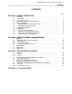
MOD 30ML Replacement for MOD 30 Instruments CONTENTS –––––––––––––––––––––––––––––––––––––––––––––––––––––––––––––––––––––––––––––––––––––––––––– CONTENTS Page SECTION 1 -PRODUCT DESCRIPTION 1.1 1.1.1 1.1.2 1.2 1.3 1.3.1 1.3.2 1.3.3 1.4 1.4.1 1.4.2 1.4.3 1.4.4 OVERVIEW . . . . . . . . . . . . . . . . . . . . . . . . . . . . . . . . . . . . . . . . . . . . . . . . . . . The Product ................................................. Related Documents ...........................................
MOD 30ML Replacement for MOD 30 Instruments CONTENTS ––––––––––––––––––––––––––––––––––––––––––––––––––––––––––––––––––––––––––––––––––––––––––– ILLUSTRATIONS Page 1-1 2-1 2-2 3-1 3-2 3-3 3-4 3-5 Location of Controller Components ................................... Example of an I/O Module Plan for a Controller Replacement . . . . . . . . . . . . . . . . Example of an I/O Module Plan for a Math Unit Replacement . . . . . . . . . . . . . . . . Communication Jumper locations ................................
MOD 30ML Replacement for MOD 30 Instruments PRODUCT DESCRIPTION SECTION 1 PRODUCT DESCRIPTION 1.1 OVERVIEW 1.1.1 The Product The MOD 30ML Replacement Instrument, Figure 1-1, can be used to replace an installed MOD 30 instrument, or to expand an existing MOD 30 installation. The replacement is a microprocessor based instrument which can be configured to perform all the PID, mathematical, sequencing, and logic functions available in MOD 30 instruments.
MOD 30ML Replacement for MOD 30 Instruments PRODUCT DESCRIPTION Front Panel Back of Housing • These modules are factory installed when ordering option package 2. Figure 1-1.
MOD 30ML Replacement for MOD 30 Instruments PRODUCT DESCRIPTION 1.1.
MOD 30ML Replacement for MOD 30 Instruments PRODUCT DESCRIPTION 1.2 EXPLANATION OF CATALOG NUMBERS The products described in this book have catalog numbers that help identify specific features. In addition, some products are assigned a serial number which can be used to track manufacturing data. The general format of the catalog number is described in this section. Specific product descriptions are provided in the following sections.
MOD 30ML Replacement for MOD 30 Instruments PRODUCT DESCRIPTION The MOD 30 complement of analog and digital inputs and outputs are supported by a combination of built-in and modular I/O in the replacement instrument. The built-in circuits reside on the carrier board and provide two analog inputs and two analog outputs. The modular I/O circuits are contained in plug-in I/O modules; they provide digital inputs, digital outputs, and additional analog inputs.
MOD 30ML Replacement for MOD 30 Instruments PRODUCT DESCRIPTION Catalog Number Description for 1800R MOD 30 Retropak ____ __ __ __ __ __- __ __ __ 0-6 07-08 09 10 11 12 13 14 15 None S T D Configured to customer's MOD 30 specifications M 3 0 MOD30 RETROPAK Base Controller 1800RZ Approvals General Purpose CE (European Community destinations only) 10 12 Power Supply 24V dc 0 I/O Options - see Note 1 Standard I/O only (two universal 1 analog inputs, two current outputs) Pre-i
MOD 30ML Replacement for MOD 30 Instruments PRODUCT DESCRIPTION 1.4 I/O MODULES The descriptions included in this section give a brief overview of the functions and features of the I/O modules which can be used in a replacement instrument.. 1.4.1 2001A Voltage Input Module The voltage input module provides dual ranges of ±10V dc and ±100 mV dc. The 10V dc range can be selected and scaled for 1 to 5 V dc by configuration to match the input of MOD 30 instruments.
MOD 30ML Replacement for MOD 30 Instruments PRODUCT DESCRIPTION 1.4.2 2006A Nonisolated Digital Input Module The Nonisolated Digital Input Module accepts switch contact closures without external power requirements. It is functionally equivalent to a digital input circuit in a MOD 30 instrument. This module uses the Digital Input Module (DIM) Block for configuration of input parameters. DIM 1 Catalog Number Description for 2006A BASE NUMBER 2006A Nonisolated Digital Input Module 2 3 4 5 1.4.
MOD 30ML Replacement for MOD 30 Instruments PRODUCT DESCRIPTION 1.4.4 2030N ICN Communication Module The ICN Communication module provides Instrument Communication Network (ICN) communications capability for the instrument when the built-in communications circuit is used to support the RS-232 communications port on the instrument front panel. The ICN is a proprietary network that allows peer-to-peer communications between the replacement instrument and MOD 30 Instruments.
MOD 30ML Replacement for MOD 30 Instruments PRODUCT DESCRIPTION 10
MOD 30ML Replacement for MOD 30 Instruments REPLACEMENT CONSIDERATIONS SECTION 2 REPLACEMENT CONSIDERATIONS 2.1 GENERAL This section provides information for planning the replacement of installed MOD 30 instruments using the MOD 30ML Replacement Instrument. The principal factors to be considered when making a replacement are as follows: • The replacement applies to the instruments only. Most MOD 30 associated equipment such as termination panels, field input boards, power supplies, etc.
MOD 30ML Replacement for MOD 30 Instruments REPLACEMENT CONSIDERATIONS 2.2 COMMUNICATIONS AND I/O SIGNALS 2.2.1 COMMUNICATIONS A built-in communications circuit supports either the RS-232 port in the front panel or communication over the ICN. If the built-in circuit is used for the RS-232 port, an ICN module must be installed to support ICN communication. The communication options are selected by positioning two jumpers. Specific instructions for locating the jumpers are provided in Section 3.4.
MOD 30ML Replacement for MOD 30 Instruments REPLACEMENT CONSIDERATIONS Table 2-1. I/O Signals Assigned to Dedicated Locations Signal Location Digital Input No. 1 Module Location S1 Digital Input No. 2 Module Location S2 Digital Input No. 3 Module Location S11 Digital Output No. 1 Module Location S3 Digital Output No. 2 Module Location S4 Digital Output No. 3 Module Location S5 Digital Output No. 4 Module Location S6 Analog Input No. 1 Built-in Volt Input No. 1 Analog Input No.
MOD 30ML Replacement for MOD 30 Instruments REPLACEMENT CONSIDERATIONS 2.2.3 I/O Signal Specification Differences In general the specifications for the replacement instrument are compatible with the MOD 30 instrument specifications. The following differences should be noted: 2.3 Specification Current Requirements Controller Indicator Math Unit MOD 30 Replacement 0.55A max 0.50A max 0.58A max 0.63A max 0.63A max 0.63A max Digital input High Level (Logic 1) Low Level (Logic 0) current load 4.
MOD 30ML Replacement for MOD 30 Instruments PRODUCT DESCRIPTION I/O MODULE PLANNING FORM FOR MOD 30 CONTROLLER MOD 30ML Replacement for Controller No. FIC-102 No Module Package (check if used) I/O Module Location I/O Module Catalog No. Digital Input No. 1 S1 2006A Digital Input No. 2 S2 2006A Digital Output No. 1 S3 2007A X Digital Output No. 2 S4 2007A X Digital Output No. 3 S5 2007A Analog Input No. 3 S9 2001A Signal Module Package* (option 2) X X Analog Input No.
MOD 30ML Replacement for MOD 30 Instruments REPLACEMENT CONSIDERATIONS 2.4 INDICATOR The MOD 30 indicator requires a single interconnecting cable to carry power and I/O signals between the instrument and the termination panel. The replacement instrument uses this same cable. The full complement of 5 I/O points can be accommodated by the replacement instrument. The I/O signals are as follows: • 3 Analog Inputs • 3 Digital Outputs (Model B only) The replacement instrument accepts analog inputs No.
MOD 30ML Replacement for MOD 30 Instruments PRODUCT DESCRIPTION I/O MODULE PLANNING FORM FOR MOD 30 MATH UNIT MOD 30ML Replacement for Controller No. FIC-101 I/O Module Catalog No. Digital Input No. 1 S1 2006A X Digital Input No. 2 S2 2006A X Digital Input No. 11 S2 2006A X Digital Output No. 1 S3 2007A X Digital Output No. 2 S4 2007A X Digital Output No. 3 S5 2007A X Digital Output No. 4 S6 2007A X Analog Input No.
MOD 30ML Replacement for MOD 30 Instruments REPLACEMENT CONSIDERATIONS 18
MOD 30ML Replacement for MOD 30 Instruments REPLACEMENT PROCEDURE SECTION 3 REPLACEMENT PROCEDURE 3.1 GENERAL Read these instructions thoroughly before starting this procedure. Installation personnel should be qualified technicians. The replacement procedure involves: • Unpacking the replacement instrument (Section 3.2) • Installing I/O modules and optional memory module if used (Section 3.3) • Setting up communications (Section 3.4) • Removing the old MOD 30 instrument(Section 3.
MOD 30ML Replacement for MOD 30 Instruments REPLACEMENT PROCEDURE 3.3 INSTALLING MODULES The I/O modules mount on the carrier board, and the optional memory module mounts on the processor board as shown in Figure 1-1. The I/O modules must be installed before placing the controller into operation. Each I/O module must be installed in a location which receives or transmits the appropriate MOD 30 signal.
MOD 30ML Replacement for MOD 30 Instruments REPLACEMENT PROCEDURE 3. Position the communication jumpers, Figure3-1, as follows: • If an ICN Module is installed, place the jumpers as shown for ICN and RS-232. • If the ICN is to use the built-in communication circuit (no ICN module), place the jumpers as shown for ICN ONLY. • If the ICN is not being used, place the jumpers as shown for RS-232 ONLY. 4.
MOD 30ML Replacement for MOD 30 Instruments REPLACEMENT PROCEDURE 3.5 REMOVING OLD MOD 30 INSTRUMENT The replacement instrument uses the cables in the existing installation. If there is a MOD 30 instrument installed in the location planned for the replacement, remove the MOD 30 instrument and its housing as follows: 1. Be sure the process is in a safe condition before removing the instrument. 2. Pull the MOD 30 instrument out of its housing. 3. Remove the back cover, Figure 3-2, from the housing. 4.
MOD 30ML Replacement for MOD 30 Instruments REPLACEMENT PROCEDURE Figure 3-2. Removing MOD 30 Instrument Housing Figure 3-3.
MOD 30ML Replacement for MOD 30 Instruments REPLACEMENT PROCEDURE 3.6 INSTALLING NEW MOD 30ML REPLACEMENT INSTRUMENT After removing a MOD 30 instrument, the replacement instrument can be installed in the same panel or bezel opening and connected to the existing MOD 30 cables using the following procedures. 3.6.1 24 Mounting 1. If the replacement instrument is not in its housing, insert the instrument and tighten the screws to draw the front panel tight against the housing.
MOD 30ML Replacement for MOD 30 Instruments REPLACEMENT PROCEDURE J1 J2 Figure 3-4. Cable Connector Locations In Back Cover 3.6.2 Electrical Connections The required power, ICN communication, and I/O signal connections to the replacement instrument are made via the cables which are installed as part of the mounting procedure.
MOD 30ML Replacement for MOD 30 Instruments REPLACEMENT PROCEDURE Power Analog Input No. 4 Analog Input No. 5 Analog Input No. 3 Analog Input No. 6 1720F Termination Panel Section Connected to J1 on Instrument 1720F Termination Panel Section Connected to J2 on Instrument Figure 3-5.
MOD 30ML Replacement for MOD 30 Instruments APPENDIX A APPENDIX A PLANNING FORMS A.1 GENERAL The forms included in this appendix may be copied as necessary to record the I/O module layout for MOD 30ML replacement instruments used to replace MOD 30 controllers and math units.
MOD 30ML Replacement for MOD 30 Instruments APPENDIX A I/O MODULE PLANNING FORM FOR MOD 30 CONTROLLER MOD 30ML Replacement for Controller No. I/O Module Location I/O Module Catalog No. Digital Input No. 1 S1 2006A Digital Input No. 2 S2 2006A Digital Output No. 1 S3 2007A Digital Output No. 2 S4 2007A Digital Output No. 3 S5 2007A Analog Input No. 3 S9 2001A Signal Module Package* (option 2) No Module Package (check if used) Analog Input No.
MOD 30ML Replacement for MOD 30 Instruments APPENDIX A I/O MODULE PLANNING FORM FOR MOD 30 MATH UNIT MOD 30ML Replacement for Controller No. I/O Module Catalog No. Digital Input No. 1 S1 2006A Digital Input No. 2 S2 2006A Digital Input No. 11 S2 2006A Digital Output No. 1 S3 2007A Digital Output No. 2 S4 2007A Digital Output No. 3 S5 2007A Digital Output No. 4 S6 2007A Analog Input No. 1 & 2 Built-in Volt Input ////////// ////////// Analog Output No.
MOD 30ML Replacement for MOD 30 Instruments APPENDIX A 30
The Company’s policy is one of continuous product improvement and the right is reserved to modify the information contained herein without notice, or to make engineering refinements that may not be reflected in this bulletin. Micromod Automation assumes no responsibility for errors that may appear in this manual. © 2004 MicroMod Automation, Inc. Printed in USA IB-1800R-M30, Issue 2 12/2004 MicroMod Automation, Inc. 75 Town Centre Drive Rochester, NY USA 14623 Tel. 585-321 9200 Fax 585-321 9291 www.