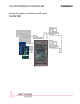
SLC RETROPAK CONTROLLER Product Description, Installation and Wiring for SLCRETRO Installation
MicroMod Automation, Inc. The Company MicroMod Automation is dedicated to improving customer efficiency by providing the most cost-effective, application-specific process solutions available. We are a highly responsive, application-focused company with years of expertise in control systems design and implementation. We are committed to teamwork, high quality manufacturing, advanced technology and unrivaled service and support.
SLC RetroPAK Controller CONTENTS CONTENTS Page SECTION 1 - PRODUCT DESCRIPTION 1.1 OVERVIEW........................................................................................................................... 1.1.1 Features............................................................................................................................. 1.1.2 Related Documents ........................................................................................................... 1.
SLC RetroPAK Controller CONTENTS SECTION 4 - MODULAR I/O CONNECTIONS 4.1 GENERAL.............................................................................................................................. 4.2 MODULAR I/O CONNECTION GUIDELINES ...................................................................... 4.3 MODULAR PROCESS INPUT CONNECTIONS .................................................................. 4.3.1 2004A SSR Input (DIM) ..............................................................
SLC RetroPAK Controller CONTENTS ILLUSTRATIONS Figure 1-1 2-1 2-2 3-1 3-2 3-3 3-4 3-5 3-6 3-7 3-8 3-9 4-1 4-2 4-3 4-4 4-5 5-1 5-2 5-3 5-4 Location of Controller Components ...................................................................................... RetroPAK Controller with Memory Module Installed ............................................................ RetroPAK Controller Mounting Dimensions..........................................................................
SLC RetroPAK Controller CONTENTS iv
SLC RetroPAK Controller PRODUCT DESCRIPTION 1 PRODUCT DESCRIPTION 1.1 OVERVIEW The SLC RetroPAK Controller, Figure 1-1, is a 3x6 instrument with a 6 line 3 bar graph configurable display, removable rear terminations, and built-in communications. The controller has two built-in 4-20mA analog inputs, two modular 4-20mA analog inputs, two milliamp built-in milliamp outputs, three digital inputs and two digital outputs. 1.1.
MOD 30ML Multiloop Controller PRODUCT DESCRIPTION Communications • Built-in RS-232 Modbus RTU communications • Modular communications supporting a peer-to-peer communications network Configuration • Full data base configuration capability using Visual Application Designer software running on a personal computer. Includes Bailey Function Code library • Display development for custom user defined displays • Custom configuration by MicroMod Automation to match existing SLC or CLC installation.
SLC RetroPAK Controller PRODUCT DESCRIPTION Front Panel Back of Housing Figure 1-1.
MOD 30ML Multiloop Controller PRODUCT DESCRIPTION 1.1.
SLC RetroPAK Controller PRODUCT DESCRIPTION 1.2 EXPLANATION OF CATALOG NUMBERS 1.2.1 General The products described in this book have catalog numbers that help identify specific features. In addition, some products are assigned a serial number which can be used to track manufacturing data. The general format of the catalog number is described in this section. Specific product descriptions are provided in the following sections.
MOD 30ML Multiloop Controller PRODUCT DESCRIPTION 1.3 BASIC HARDWARE 1.3.1 RETROPAK CONTROLLER The SLC RetroPAK controller, Figure 1-1, s designed for mounting in a panel with a 15.75inch depth. The instrument housing contains a 50-point termination facility which accepts all instrument I/O, communications, and power connections. A separate grounding stud provides a safety ground connection.
SLC RetroPAK Controller PRODUCT DESCRIPTION 1.3.2 1800P Identity Module The identity module, Figure 1-1, gives the instrument a specific level of process and communications functionality. The 1800P module is factory installed and provides the capability to execute a user-configured database which consists of built-in and modular I/O handling capabilities, PID functionality, and a collection of other control related functions.
MOD 30ML Multiloop Controller PRODUCT DESCRIPTION 1.3.4 2010P Memory Module The optional memory module plugs directly into the CPU board, Figure 1-1, and provides a mechanism for porting a database from one instrument to another. An instrument with this option can upload from or download to this module. The memory module has a write protect setting to prevent accidental erasures.
SLC RetroPAK Controller PRODUCT DESCRIPTION 1.4 I/O MODULES The descriptions included in this section give a brief overview of the functions and features of the I/O modules. 1.4.1 2012A Current Input Module (with 2-wire transmitter power) This module is designed specifically for two-wire transmitters and provides the necessary 24 V DC current limited supply to power the transmitter. An internal current sense resistor converts the current to a voltage for application to the A/D converter.
MOD 30ML Multiloop Controller PRODUCT DESCRIPTION 1.4.3 2005A Solid-State Relay Output Module The Solid-State Relay Output module provides the necessary interfacing for AC or DC digital outputs when high isolation voltages are required (250V rms isolation limitation through connection terminals). This module uses the Digital Output Module (DOM) Block for configuration of output parameters. DOM Catalog Number Description for 2005A BASE NUMBER 2005A Nonisolated Digital Input Module 1.
SLC RetroPAK Controller PRODUCT DESCRIPTION 1.5.2 2030F ICN Terminator The ICN Terminator is used to provide a termination scheme for a peer-to-peer ICN network. One termination is required per ICN.
MOD 30ML Multiloop Controller PRODUCT DESCRIPTION 12
SLC RetroPAK Controller MODULAR I/O CONNECTIONS 4 MODULAR I/O CONNECTIONS Figure 4-1. Terminal Identifications for Modular I/O 4.1 GENERAL Read this section thoroughly before making any connections to modules. Installation personnel should be qualified technicians. Observe all electrical code requirements and safety standards applicable to these wiring procedures. Specific instructions and connection diagrams for the various input and output modules are provided in Sections 4.3 and 4.4.
SLC RetroPAK Controller MODULAR I/O CONNECTIONS 3. Route low-level signal wiring from the top left hand side of the housing and ac voltage wiring from the bottom right hand side and distribute to appropriate terminals. 4. Use a small, flat-head screwdriver to loosen appropriate connection screws and clamps on terminal blocks. 5. Strip approximately 5/16 inch (8 mm) of insulation from the end of each wire, insert wires at assigned terminals, and secure terminal screws and clamps.
SLC RetroPAK Controller MODULAR I/O CONNECTIONS Figure 4-2.
SLC RetroPAK Controller MODULAR I/O CONNECTIONS 4.3.2 2012A Current Inputs (VCIM) Make current input connections as shown in Figure 4-5 for 2-Wire Transmitter (2012A). 2-Wire Transmitter (2012A) The 2-wire version of the milliampere input receives its loop current from a 24V dc current supply built into the module. This current supply is automatically connected in the circuit when the 2-wire input connection is made. The load on the transmitter is nominally 100 ohms.
SLC RetroPAK Controller MODULAR I/O CONNECTIONS 4.4 MODULAR OUTPUT CONNECTIONS This section describes the process input connections for the following input module types: • 4.4.1 2005A Solid-State Relay Output Module - Section 4.4.2 2005A SSR Output (DOM) Recommended connections to a customer relay are shown in Figure 4-11. Make SSR output connections as shown in Figure 4-12. DC output modules are used for controlling or switching DC loads.
SLC RetroPAK Controller MODULAR I/O CONNECTIONS Figure 4-5.
SLC RetroPAK Controller PRODUCT DESCRIPTION 1 PRODUCT DESCRIPTION 1.1 OVERVIEW The SLC RetroPAK Controller, Figure 1-1, is a 3x6 instrument with a 6 line 3 bar graph configurable display, removable rear terminations, and built-in communications. The controller has two built-in 4-20mA analog inputs, two modular 4-20mA analog inputs, two milliamp built-in milliamp outputs, three digital inputs and two digital outputs. 1.1.
MOD 30ML Multiloop Controller PRODUCT DESCRIPTION Communications • Built-in RS-232 Modbus RTU communications • Modular communications supporting a peer-to-peer communications network Configuration • Full data base configuration capability using Visual Application Designer software running on a personal computer. Includes Bailey Function Code library • Display development for custom user defined displays • Custom configuration by MicroMod Automation to match existing SLC or CLC installation.
SLC RetroPAK Controller PRODUCT DESCRIPTION Front Panel Back of Housing Figure 1-1.
MOD 30ML Multiloop Controller PRODUCT DESCRIPTION 1.1.
SLC RetroPAK Controller PRODUCT DESCRIPTION 1.2 EXPLANATION OF CATALOG NUMBERS 1.2.1 General The products described in this book have catalog numbers that help identify specific features. In addition, some products are assigned a serial number which can be used to track manufacturing data. The general format of the catalog number is described in this section. Specific product descriptions are provided in the following sections.
MOD 30ML Multiloop Controller PRODUCT DESCRIPTION 1.3 BASIC HARDWARE 1.3.1 RETROPAK CONTROLLER The SLC RetroPAK controller, Figure 1-1, s designed for mounting in a panel with a 15.75inch depth. The instrument housing contains a 50-point termination facility which accepts all instrument I/O, communications, and power connections. A separate grounding stud provides a safety ground connection.
SLC RetroPAK Controller PRODUCT DESCRIPTION 1.3.2 1800P Identity Module The identity module, Figure 1-1, gives the instrument a specific level of process and communications functionality. The 1800P module is factory installed and provides the capability to execute a user-configured database which consists of built-in and modular I/O handling capabilities, PID functionality, and a collection of other control related functions.
MOD 30ML Multiloop Controller PRODUCT DESCRIPTION 1.3.4 2010P Memory Module The optional memory module plugs directly into the CPU board, Figure 1-1, and provides a mechanism for porting a database from one instrument to another. An instrument with this option can upload from or download to this module. The memory module has a write protect setting to prevent accidental erasures.
SLC RetroPAK Controller PRODUCT DESCRIPTION 1.4 I/O MODULES The descriptions included in this section give a brief overview of the functions and features of the I/O modules. 1.4.1 2012A Current Input Module (with 2-wire transmitter power) This module is designed specifically for two-wire transmitters and provides the necessary 24 V DC current limited supply to power the transmitter. An internal current sense resistor converts the current to a voltage for application to the A/D converter.
MOD 30ML Multiloop Controller PRODUCT DESCRIPTION 1.4.3 2005A Solid-State Relay Output Module The Solid-State Relay Output module provides the necessary interfacing for AC or DC digital outputs when high isolation voltages are required (250V rms isolation limitation through connection terminals). This module uses the Digital Output Module (DOM) Block for configuration of output parameters. DOM Catalog Number Description for 2005A BASE NUMBER 2005A Nonisolated Digital Input Module 1.
SLC RetroPAK Controller PRODUCT DESCRIPTION 1.5.2 2030F ICN Terminator The ICN Terminator is used to provide a termination scheme for a peer-to-peer ICN network. One termination is required per ICN.
MOD 30ML Multiloop Controller PRODUCT DESCRIPTION 12
SLC RetroPAK Controller MECHANICAL INSTALLATION 2 MECHANICAL INSTALLATION 2.1 GENERAL Read these instructions thoroughly before starting installation. Installation personnel should be qualified technicians. Mechanical installation involves: 2.1.1 • Unpacking (Section 2.2) • Planning and Installing optional I/O and memory modules if these items are being used (Section 2.3) • Mounting (Section 2.4) Displays and Cleaning The display is protected by an overlay that can be removed after installation.
MOD 30ML Multiloop Controller MECHANICAL INSTALLATION 2.3 USING THE MEMORY MODULE The optional memory module plugs directly into the CPU board and can be used to back up a controller database, or transfer a database from one instrument to another. Figure 2-1. Controller with Memory Module Installed A controller database can be copied into the Memory Module and the module removed for safekeeping. Data retention, when the module is not installed on a working instrument, is typically 10 years.
SLC RetroPAK Controller MECHANICAL INSTALLATION 2. Position the memory module over the metal plate on the carrier board. Orient the memory module so that the catalog number label is visible when the module is plugged into the connector on the CPU board. 3. Slide the memory module onto the connector on the CPU board, making sure it is firmly seated on the connector and the metal retaining bracket is in place at the rear of the module.
MOD 30ML Multiloop Controller MECHANICAL INSTALLATION Normal / Module Load Switch This switch has two positions: NORMAL and MODULE LOAD. Normal Position With this switch in the NORMAL position, data is automatically transferred from the Memory Module to the instrument, on power up only. This is also referred to as downloading a database from the Memory Module. Loads Memory Module database into controller on power up. Allows updates to Memory Module during operation.
SLC RetroPAK Controller MECHANICAL INSTALLATION The following table shows the data flow for each combination of switch positions: SWITCH POSITION SWITCH 1 SWITCH 2 READ/WRITE READ ONLY X NORMAL MODULE LOAD X X X X X X X Database transfer from memory module to controller on power up. Memory module updated every 50ms by controller during operation. Complete contents of controller memory transferred to memory module (UPLOAD). Existing program is overwritten.
MOD 30ML Multiloop Controller MECHANICAL INSTALLATION SLC RETROPAK I/O LAYOUT Controller No. Built-in I/O Input 1: 4-20mA w/ 24Vdc Transmitter Power Supply Output 1: 20 mA Input 2: 4-20mA w/ 24 Vdc Transmitter Power Supply Output 2: 20 mA Communications: RS-232 Modbus (port 1) Modular I/O I/O Module Locations No. Module No. Module No.
SLC RetroPAK Controller MECHANICAL INSTALLATION 2.4 MOUNTING The controller must be installed in an approved enclosure or installed in a means acceptable to the authority having jurisdiction for electrical installations. ∆WARNING Do not install a RetroPAK controller in a residential, commercial or light industrial environment in the European Union. Select a mounting location where: • There is minimum vibration.
MOD 30ML Multiloop Controller MECHANICAL INSTALLATION MOUNTING DIMENSIONS FOR SLC RETROPAK Center-to-Center Distance Recommended Minimum Inches 0.60 0.87 1.13 2.69 2.87 3.50 4.00 mm 15.2 22.1 28.7 68.3 72.9 88.9 101.6 F G 4 3.5 8 7 Inches 5.43 5.47 5.69 7.00 8.00 15.75 mm 137.9 138.9 144.5 177.8 203.2 400.0 1.5 inch (38.1mm) clearance for optional communications jack. NOTES: 1.
SLC RetroPAK Controller POWER, GROUNDING, AND BUILT-IN I/O CONNECTIONS SECTION 3 POWER, GROUNDING, AND BUILT-IN I/O CONNECTIONS 3.1 GENERAL Read this section thoroughly before making any connections. Installation personnel should be qualified technicians. Observe all electrical code requirements and safety standards applicable to these wiring procedures. Specific instructions and connection diagrams for the various built-in inputs and outputs are provided in Sections 3.3 through 3.7.
SLC RetroPAK Controller POWER, GROUNDING, AND BUILT-IN I/O CONNECTIONS Figure 3-1.
SLC RetroPAK Controller POWER, GROUNDING, AND BUILT-IN I/O CONNECTIONS 5. Use a small flat-head screwdriver to loosen appropriate connection screws and clamps on terminal blocks. 6. Strip approximately 5/16 inch (8 mm) of insulation from the end of each wire, insert wires at assigned terminals and secure terminal screws and clamps. 7. Make wiring connections using the following procedures: a. Power connections - Section 3.3. b. Ground and shield connections - Section 3.4. c.
SLC RetroPAK Controller POWER, GROUNDING, AND BUILT-IN I/O CONNECTIONS 3.3 POWER CONNECTIONS ∆ WARNING Avoid electrical shock. AC power wiring must not be connected at the distribution panel (ac source) until all wiring procedures are completed. All power wiring must be in compliance with the requirements of the National Electrical Code or Canadian Electrical Code.
SLC RetroPAK Controller POWER, GROUNDING, AND BUILT-IN I/O CONNECTIONS 3.4 GROUND CONNECTIONS A protective ground terminal (green metal stud) is provided at the bottom of the terminal blocks near the power connections, Figure 3-1. Connect this terminal directly to the plant safety ground system. This terminal is to be used only for the protective ground conductor. Keep the ground wire as short as possible and use the largest practical wire gage. 3.4.
SLC RetroPAK Controller POWER, GROUNDING, AND BUILT-IN I/O CONNECTIONS 3.4.4 Noise Prevention Measures Primary power circuit distribution system: • Ideally, each microprocessor-based device should be provided with an independent dedicated power source. Where this approach is not feasible due to space availability or cost per device, an acceptable alternative is to install constant voltage, isolation transformers in the branch circuit where the microprocessor-based device is installed.
SLC RetroPAK Controller POWER, GROUNDING, AND BUILT-IN I/O CONNECTIONS Figure 3-2. Terminal Identifications for Built-in I/O 3.5 BUILT-IN PROCESS INPUT CONNECTIONS Built-in inputs 1 and 2 are isolated universal analog inputs which accept volts dc, millivolts dc, milliamps dc (includes 2-wire transmitters), RTD, Thermocouple, and resistance signals. Connections to these inputs are made to the terminals shown in Figure 3-2.
SLC RetroPAK Controller POWER, GROUNDING, AND BUILT-IN I/O CONNECTIONS 3.5.1 Built-In Voltage, Millivolt and Thermocouple Inputs Make volt, millivolt and thermocouple input connections as shown in Figure 3.3. Always connect the first thermocouple input to the I/O 1 terminals to enable automatic cold junction compensation for all thermocouple inputs. GROUNDED UNGROUNDED V, mV or tc Source - + V, mV or tc Source G - + G Shield to be left unconnected at this end.
SLC RetroPAK Controller POWER, GROUNDING, AND BUILT-IN I/O CONNECTIONS 3.5.2 Built-In RTD Input Make RTD input connections as shown in Figure 3-4. See Section 4.3.6 for a listing of materials, standards and sample RTDs supported by the instrument software. 2-WIRE RTD 3-WIRE RTD t° t° Note: 4-Wire RTD connected same as 3-Wire RTD with fourth lead unused Shield Shield to Chassis Terminal to instrument ground to Chassis Terminal to instrument ground Figure 3-4.
SLC RetroPAK Controller POWER, GROUNDING, AND BUILT-IN I/O CONNECTIONS 3.5.3 Built-In Current Input - 2-Wire Transmitter Make input connections from a 2-wire transmitter as shown in Figure 3-5. 22mA Maximum Loop Current When the maximum required loop current is 22 mA or less, make connections as shown in the left hand view of Figure 3-5. In this connection arrangement, the 2-wire loop receives its current from a 24V supply in the controller.
SLC RetroPAK Controller POWER, GROUNDING, AND BUILT-IN I/O CONNECTIONS 3.5.4 Built-In Current Input - Non 2-Wire Transmitter Make current input connections from a non 2-wire transmitter as shown in Figure 3-6. Note that the transmitter must be powered from an external source which meets the transmitter power specifications. Non 2-Wire Transmitter Power - + G Note: Non 2-Wire transmitter may also be ungrounded. Shield to be left unconnected at this end. to instrument ground Figure 3-6.
SLC RetroPAK Controller POWER, GROUNDING, AND BUILT-IN I/O CONNECTIONS 3.5.5 Built-In Resistance Input The resistance input can be used to monitor a resistance which changes in proportion to a process related value such as a set-point. Make resistance input connections as shown in Figure 3-7. The resistance input can also be used for a 2-wire RTD, which is not on the list of supported RTDs in Section 4.3.6. Make the 2-wire RTD connections as shown in Figure 3-4.
SLC RetroPAK Controller POWER, GROUNDING, AND BUILT-IN I/O CONNECTIONS 3.6 BUILT-IN OUTPUT CONNECTIONS Built-in outputs 1 and 2 are milliamp analog control outputs. Connections to these outputs are made as shown in Figure 3-2. The output circuit diagrams, Figures 3-8 and 3-9 identify the Output 1 terminals as I/O 1 and the Output 2 terminals as I/O 2. The built-in outputs are always milliamp signals.
SLC RetroPAK Controller POWER, GROUNDING, AND BUILT-IN I/O CONNECTIONS 34
SLC RetroPAK Controller COMMUNICATIONS CONNECTIONS 5 COMMUNICATIONS CONNECTIONS Figure 5-1. Terminal Identifications for Communications Network Connections 5.1 GENERAL Read this section thoroughly before making connections. Installation personnel should be qualified technicians. The controller provides communications capability for both ICN (peer-to-peer) and Modbus networks, permitting the controller to communicate on two different networks simultaneously.
SLC RetroPAK Controller COMMUNICATIONS CONNECTIONS 5.2 COMMUNICATION CONNECTION GUIDELINES The wiring connections described in this section are made with the controller installed in its operating location and with the power off. All connection terminals are located under a cover on the back of the instrument housing. Figure 5-1 shows the communication connection terminals with the cover removed. The recommended procedure for making communications connections is as follows: 1.
SLC RetroPAK Controller COMMUNICATIONS CONNECTIONS Figure 5-2. Locations for Port 1 Communications Jumper – Built-in Circuit 5.3 FRONT PANEL RS-232 COMMUNICATIONS CONNECTION The RS-232 communication port in the instrument front panel is used exclusively for data base configuration via connection of a portable computer. Use of this RS-232 port is subject to the following requirements: • Connection to the port must be made using a cable which is available as an accessory to the instrument.
SLC RetroPAK Controller COMMUNICATIONS CONNECTIONS • The instrument data base must be configured to provide RS-232 communication on the built-in circuit; this is the default configuration. When the built-in RS-232 circuit is being used for network communication, making a connection to the front panel RS-232 port disables the network receive function so that the instrument can receive data only from the device connected to the port. The transmit line is not affected. 5.
SLC RetroPAK Controller COMMUNICATIONS CONNECTIONS Figure 5-3.
SLC RetroPAK Controller COMMUNICATIONS CONNECTIONS 5.4.3 Termination One set of ICN termination resistors must be installed on each ICN to prevent noise from being picked up by the ICN circuitry and generating a diagnostic alarm. The ICN termination scheme requires a nominal 24 volt DC power supply that can supply 15.4 mA. This supply is provided by both the built-in and modular circuits. The termination resistor network is provided in a 2030FZ00001A ICN Terminator.
SLC RetroPAK Controller COMMUNICATIONS CONNECTIONS Connections for a typical RS-232 Modbus network using the built-in circuit are shown in Figure 5-4. Personal Computer or Controller Built-in connections use communications Port 1. Locate jumper as shown in Figure 5-2. RX TX TX RX MODBUS MASTER COM COM Built-in Communication ! Caution. Disconnect power before wiring. Refer to terminal connections. to instrument ground if PC is isolated Figure 5-4.
The Company’s policy is one of continuous product improvement and the right is reserved to modify the information contained herein without notice, or to make engineering refinements that may not be reflected in this bulletin. Micromod Automation assumes no responsibility for errors that may appear in this manual. © 2005 MicroMod Automation, Inc. Printed in USA IB-SLCRETRO-INS, Issue 1 March 2005 MicroMod Automation, Inc. 75 Town Centre Drive Rochester, NY USA 14623 Tel. 585-321 9200 Fax 585-321 9291 www.