
Installation Manual User Manual
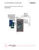


SLC RetroPAK Controller
CONTENTS
iii
ILLUSTRATIONS
Figure Page
1-1 Location of Controller Components ...................................................................................... 3
2-1 RetroPAK Controller with Memory Module Installed ............................................................ 14
2-2 RetroPAK Controller Mounting Dimensions.......................................................................... 20
3-1 Electrical Connection Terminals ........................................................................................... 22
3-2 Terminal Identifications for Built-in I/O.................................................................................. 27
3-3 Built-in Voltage, Millivolt and Thermocouple Input Connections........................................... 28
3-4 Built-in RTD Input Connections............................................................................................. 29
3-5 Built-in 2-Wire Milliampere Current Input Connections......................................................... 30
3-6 Built-in Non 2-Wire Current Input Connections .................................................................... 31
3-7 Built-In Resistance Input Connections.................................................................................. 32
3-8 Built-in Milliampere Output Connections............................................................................... 33
3-9 Built-in Voltage Output Connections..................................................................................... 33
4-1 Terminal Identifications for Modular I/O................................................................................ 35
4-2 Typical Connections for a 2004A Solid State Relay Input Module ....................................... 37
4-3 Typical Connections for a 2012A Current Input Module with 2-Wire Transmitter Power..... 38
4-4 Recommended Connection to Solid State Relay.................................................................. 39
4-5 Typical Connections for a 2005A Solid State Relay Output Module .................................... 40
5-1 Terminal Identifications for Communications Network Connections .................................... 41
5-2 Locations for Port 1 Communications Jumper...................................................................... 43
5-3 ICN Connections Modular Communication Circuits ............................................................. 45
5-4 Typical Network Connections for Built-In Modbus RS-232 Communication ....................... 47