User’s Manual SP5050/SP5052/SP5054 IP Telephony Gateway, FXO Interface Website: http://www.micronet.
1. INTRODUCTION ....................................................................................................................................... 3 1.1 FEATURES AND SPECIFICATION ................................................................................................................. 3 1.2 APPEARANCE ........................................................................................................................................... 4 2. SYSTEM OPERATING PROCEDURE ........................
1. Introduction The Micronet SP5050 Series FXO gateway provides voice/fax service over IP network with H.323 v3 protocol. By connecting to your existing ADSL or cable modem service, which allows the use of a single, network for voice and fax services with consequent saving in network infrastructure and greatly reduced telephone charges. Ideal solution for providing low cost communications between headquarters and branch offices in the world, as well as for SOHO and office telephony applications.
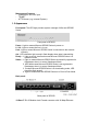
Management Features: - Console port: RS-232C port - TELNET - HTTP Brower (e.g. Internet Explorer) 1.2 Appearance Front panel: The LED light provides system message of Micronet SP5050 Series. Front panel of SP5050 Power : Light on means Micronet SP5050 Series is power on. L1-L6 : Light on means the line is in use. Link : Light on means Micronet SP5050 Series is connected to the network correctly. Act : LED should be light on and in flash display when data is transmitting. Ready : 1.
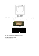
PIN 1, 2: Transmit PIN 3, 6: Receive COM: RS232 console port (9-pin Male connector, as the same as the computer). Male connector (as the same as the PC) 9 PIN D-SUB MALE at the VoIP FXO gateway Pin Name Dir Description Å Receive Data 2 RXD Æ Transmit Data 3 TXD 5 GND ─ System Ground L1 ~ L6: RJ-11 (PSTN or Extension Line of PBX) On / Off: Power switch on/off. 100 - 240 VAC: AC Power supply.
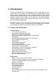
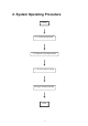
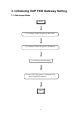
2. System Operating Procedure START 2.1 System Requirement 2.2 Telephone Line Requirement 2.3 IP Environment Setting 2.
2.1 System Requirement 1. One PC (a) Pentium 100 or above, 64 MB DRAM, Windows 98 or above. (b) Network card (RJ-45) & COM port 2. One standard RS-232 straight cable with two female connectors depended on the different model. 3. PSTN lines / PBX extension lines (up to 4 lines). 4. Software tools (a) Hyper terminal, telnet (Windows OS included) (b) Gatekeeper (optional) 2.2 Telephone Line Requirement Two kinds of analog lines can be connected to RJ-11 of VoIP FXO Gateway. 1.
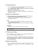
2. Define a name such as ‘SP5050 Gateway’ for this new connection. 3. After pressing OK button, the next window popping up is necessary to connect choose COM Port.
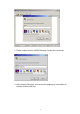
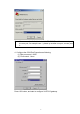
Note: Some connection failed is derived the PC COM Port. If user cannot open the com port, for example com 1, please try another com port, ex.com port 2. 4. Configure the COM Port Properties as following: (1) Bits per second : 9600 (2) Flow control : None Press ‘OK’ button, and start to configure VoIP FXO gateway.
3. Initializing VoIP FXO Gateway Setting 3.
(a) Configure VoIP FXO gateway Password It is important for the first time user to follow the operation procedure. 1. Power on the VoIP FXO gateway and the sentence “Please wait while system is initializing…………S” is displayed. Attached TCP/IP interface to cpm unit 0 Attaching interface lo0...done Please wait while system is initializing .......... S 2. Wait around 40 seconds, the login name and password are requested. Attached TCP/IP interface to cpm unit 0 Attaching interface lo0...
(b) Configure VoIP FXO gateway IP Address Use “ifaddr” command to set up VoIP FXO gateway’s IP address and related network information. An example is demonstrated below: usr/config$ ifaddr –ip 10.1.1.1 –mask 255.2555.255.0 –gate 10.1.1.254 Note: this is to assign VoIP FXO gateway an IP address of “10.1.1.1”, subnet mask “255.255.255.0”, and default IP gateway “10.1.1.254”. (c) Gatekeeper Mode Settings To assign a gatekeeper address for VoIP FXO gateway, and define its own registered ID and phone number.
Note: mode 1 is for Peer-To-Peer (non-gk) mode, while mode 0 is for GK mode. 2. Configure Phonebook, using “pbook” command. Users can refer to chapter 5.11 [pbook] command for more information. usr/config$ pbook –add name TEST1 ip 10.1.1.1 e164 10 Note: The command is to add a record onto Phonebook. After the command completed, you can type “pbook –print” to see if the input record is correct.
Dynamic IP Address –usr/config$ ifaddr –ipsharing 1 Note: With Dynamic WAN IP Address, a Gatekeeper with a valid IP address for VoIP FXO gateway is a must. In other word, it is not workable in Peer-to-Peer mode while dynamic WAN IP Address. IP Sharing device must have a function to do IP/Port mapping. Some is named as DMZ, some is named as virtual server. The VoIP messages from WAN have to completely pass forward to the LAN.
4. Disconnect Tone Configuration This application note is going to describe the procedures of configuring the disconnect tone on VoIP FXO gateway in order to release LINE ports of VoIP FXO gateway after PSTN/PBX caller party is hung up. 4.1 What is Disconnect Tone IP-Network IP Side VoIP PSTN side FXO gateway Other VoIP devices PSTN or PBX Caller A caller make a telephone call to gateway from PSTN side, VoIP FXO gateway will answer the call automatically.
Otherwise it may be released after one minute or lock this LINE permanently. The tone table parameters are shown as follows. LowFreq 480 : Low frequency is 480 HZ HighFreq 620 : High frequency is 620 HZ LowFreqLevel 8 : Low frequency level received range from PSTN/PBX HighFreqLevel 8 : High frequency level received range from PSTN/PBX TOn1 50 : Disconnect tone cadence ON time is 0.5 seconds TOff1 50 : Disconnect tone cadence OFF time is 0.
620/480, take the following procedures. 620/479 620/480 620/481 621/479 621/480 621/481 619/479 619/480 619/481 If the line port of gateway was locked, please use “hangup 0” command to release LINE 1, “hanhup 1” to release LINE 2…etc. 4.4 Adjust Input Tone Level Sometimes the disconnect tone level is too low to be detected by VoIP FXO gateway. You can increase input gain from the following command. voice -volume input xx commit reboot xx is the input gain parameters. The maximum number is 35.
5. Command lists 5.1 [help] command Type help or man or ? to list all the available command.
Open debug message will show up specific information while VoIP FXO gateway is in operation. After executing the debug command, it should execute command debug -open as well. One example is demonstrated below. usr/config$ debug -add h323 vp usr/config$ debug -open Parameters Usage: -status Display the enabled debug flags. -add Add debug flag. -- h323 : h323 related information -- vp : voice related information -delete Remove specified debug flag. -open Start to show debug messages.
Warning: Once users execute flash –clean, all the configurations of VoIP FXO gateway will be cleaned. This can only be executed by user who log in with root 5.6 [commit] command Save changes after configuring the VoIP FXO gateway. usr/config$ commit This may take a few seconds, please wait.... Commit to flash memory ok! usr/config$ Note: Users should use commit to save modified value, or they will not be activated after system reboot. 5.
ifaddr -timezone 8 Parameters Usage: -print print current IP setting -ip assigned IP address for VoIP FXO gateway -mask internet subnet mask -gate IP default gateway -dhcp Dynamic Host Configuration (1 = ON; 0 = OFF) -sntp Simple Network Time Protocol (1 = ON; 0 = OFF) When SNTP function is activated, users have to specify a SNTP server as network time source. An example is demonstrated below: usr/config$ ifaddr -sntp 1 10.1.1.1 while 10.1.1.1 stands for SNTP server’s IP address.
no answer from 210.54.23.129 usr/config$ ping 192.168.4.121 PING 192.168.4.121: 56 data bytes 64 bytes from 192.168.4.121: icmp_seq=0. time=5. ms 64 bytes from 192.168.4.121: icmp_seq=1. time=0. ms 64 bytes from 192.168.4.121: icmp_seq=2. time=0. ms 64 bytes from 192.168.4.121: icmp_seq=3. time=0. ms ----192.168.4.121 PING Statistics---4 packets transmitted, 4 packets received, 0% packet loss round-trip (ms) min/avg/max = 0/1/5 5.
Please wait for Writing...block 1 Please wait for Writing...block 2 Replay New Greeting Voice?(y/n): Disconnect Tone Analysis : please follow instructions on screen (Selection 2). First call in line1 of VoIP FXO gateway from PSTN side (now can’t hear greeting), hang up the phone and press “enter” to start record disconnect tone. Finally, choose “y/n” to save data analyzed or not.
3.exit. -------------------------------------------------Please input function(1~3): 3 Are you sure to EXIT?!(y/n): y usr/config$ 5.11 [pbook] command Phone Book function allows users to define their own numbers, which mapping to real IP address. It is effective only in peer-to-peer mode. When adding a record to Phone Book, users do not have to reboot the machine, and the record will be effective immediately.
phone number. Note: means the sequence number in phone book. If users do not request a specific index number in phone book, VoIP FXO gateway will give each record a automatic sequence number as index. -add -search -delete -insert -modify add a new record to phone book. When adding a record, users have to specify name, ip, and e164 number to complete the command. search a record in phone book. The searching criteria can be name, ip, or e164. delete a specific record.
5.12 [pppoe] Display PPPoE related information. PPPoE device information and configuration Usage: pppoe [-print]|[-open]|[-close] pppoe [-dev on/off][-id username][-pwd password] -print Display PPPoE device information. -dev Enable(=1) or Disable(=0) device. -open Open PPPoE connection. -close Disconnect PPPoE connection. -id Connection user name. -pwd Connection password. -reboot Reboot after remote host disconnection. Paremeter Usage: -print print PPPoE status.
-idto -eod button, The duration of two pressed digits in dial mode Digit type of end of dialing. ( 0:No end of dialing, 1:[*] 2:[#] button ) Choose line seizure mode (None/UCD). Config GW to accept 2nd dtmf set. In this mode, device from IP side needs to dial GW's E164, wait for PSTN dialtone, and then dial out. -drule Specify digits to be filtered/dropped/inserted before making an outgoing IP call or after receving an incoming IP call. -askpin PIN code prompt before greeting.
1 (Direct In Line Service): This feature must be implemented in a pair of FXO products in Gatekeeper mode and set bureau –table command. In Direct In Line Service VoIP FXO gateway will connected via gatekeeper to pre-defined E.164 number. For example: $bureau –table 1 192.168.4.184 123 (please refer to 5.21 bureau command) If L1 of VoIP FXO gateway is assigned to pre-defined E.164 number 123 in Direct in line mode.
- idto - eod: - seizure value is set to enable all ports. The duration of two pressed digits in dial mode Digit type of end of dialing. ( 0:No end of dialing, 1:[*] button, 2:[#]button ) line seizure mode. None (0): When calling from IP side, choose L1 every time if it is available. UCD (1): When calls from IP side, choose L1 for the first time, and L2 for the 2nd time, (cyclic) Note: Do not enable this function together with group (please refer to 5.18).
for response. If the other party cannot respond the message in 10 seconds, VoIP FXO gateway will regard the opposite party as IDLE state and disconnect the call. When CallAlive is deactivated, RoundTripDelay message will not be sent during connection. - keypad keypad type when relay DTMF signal. 0 : In-Band 1 : h.245 alphanumeric 2 : h.245 signal type 3 : q.931 user info - pincode To specify 2 sets of pincode.
-gwtype -ras -range -respto -connto Register as Gateway (1) or Terminal (0) type Gatekeeper RAS port (1024~65535). Dynamically allocated port range (1500~65535). Max waiting time for 1st response to a new call (1~200). Max waiting time for call establishment after receiving 1st response of a new call (1~20000). Note: H.245 port configuration is not available now. Options -gk -e164 -alias -multi -ttl -gkfind -ras are ignored when RAS mode is configured as Peer-to-Peer mode. Example: h323 -gk 210.59.163.
-e164 e164 number, which is registered as phone number in gatekeeper. -alias h323 ID, a identification in h323 world for other parties’ recognition. The field might be used as a key of authorization or accounting in some VoIP application. It is recommended to assign a special name, or it might conflict with other devices. -gkdis Switch ON or OFF of gatekeeper discovery function (1 = ON; 0 = OFF). When it’s ON, VoIP FXO gateway will send GRQ with GK ID to default gatekeeper.
Usage: gk [-add type1 [[type2]...]] [-delete h323] [-ttl value [-enable 0/1] [-security enable/disable] -print -enable -ttl -add Display the enabled debug flags. Enable simple gatekeeper Set TTL value Add dynamic endpoint (h323 ID, E164, IP, port, type) -delete Delete dynamic endpoint -security enable Enable security check -security disable Disable security check -security add Add security record -security delete Delete security record Example: gk -add h323 256 192.168.1.
usr/config$ voice Voice codec setting information and configuration Usage: voice [-send [G723 ms] [G711A ms] [G711U ms] [G729A ms] ] [-volume [voice level] [input level] [dtmf level]] [-nscng G723 used] [-echo used] [-mindelay t1] [-maxdelay t2] [-optfactor f] voice -print voice -priority [G723] [G711A] [G711U] [G729A] -print Display voice codec information and configuration. -send Specify sending packet size. G.723 (30/60 ms) G.711A (20/40/60 ms) G.711U (20/40/60 ms) G.
-nscng silence suppression and comfort noise generation setting (1 = ON; 0 = OFF). It is applicable to G.723 codec only. An example is demonstrated below: usr/config$ voice -nscng g723 1 -mindelay -maxdelay the minimum jitter buffer size. (Default value= 90 ms) the minimum jitter buffer size. (Default value= 150 ms) usr/config$ voice –mindelay 90 –maxdelay 150 -optfacor 7 -echo activate each canceller (1 = ON; 0 = OFF).
-rtptype -rtcptype -sigdelay -rtpdelay -rtcpdelay -sigthruput configure TOS type of RTP packets from 0 to 7 configure TOS type of RTCP packets from 0 to 7 configure signaling packets as normal delay or low delay configure RTP packets as normal delay or low delay configure RTCP packets as normal delay or low delay configure signaling packets as normal throughput or high throughput -rtpthruput configure RTP packets as normal throughput or high throughput -rtcpthruput configure RTCP packets as normal throughp
-t38 -fstart -tunnel -h245fs Example: support support support T.38(FAX) enabled/disabled. Fast start enabled/disabled. H245 Tunneling enabled/disabled. H245 separate channel after faststart. -fstart 1 -tunnel 0 -h245fs 1 Parameter Usages: -print print current setting in support command. -t38 to switch ON/OFF (1 = ON; 0 = OFF) T.38 function.T.38 function is for FAX. If user will use FAX machines, please switch on T.38 function. -fstart to switch ON/OFF (1 = ON; 0 = OFF) FastStart function.
-enable -disable -number -pattern -e164 Enable PSTN Grouping Disable PSTN Grouping Set number of divided groups Set number of members in each group Set E.
-table Set Hot line/Line To Line information. (Port range: 1~2) Note: Hotline feature should be used together with: $sysconf -service 2 (HotLine service) $sysconf -2nddial 0 (2nddial off) $h323 -mode 1 (peer-to-peer mode) Line To Line feature should be used together with: $sysconf -service 2 (HotLine service/Line To Line ) $sysconf -2nddial 1 (2nddial on) $h323 -mode 1 (peer-to-peer mode) Example: bureau -pstn 2011 2012 bureau -table 1 192.168.4.69 628 2 192.168.4.
5.22 [prefix] command This function can do digits replacement of incoming call from IP side or PSTN side. usr/config$ prefix Prefix setting information and configuration Usage: prefix [-pstnrule index oldnumber newnumber (index = 1 ~ 6)] [-iprule index oldnumber newnumber (index = 1 ~ 6)] prefix -print -print Display prefix information and configuration. -pstnrule Set PSTN incoming prefix rule information. -iprule Set IP incoming prefix rule information.
-dspcore update DSP kernel code(optional) -dspapp update DSP application code(optional) -rbpcm update RingBack Tone PCM file(optional) -htpcm update Hold Tone PCM file(optional) -greeting update Greetings PCM file(optional) -askpin update AskPin file(optional) -s IP address of TFTP/FTP server (mandatory) -f file name(mandatory) -method download via TFTP/FTP (TFTP: mode=0, FTP: mode=1) -ftp specify username and password for FTP Note: This command can run select one option in 'app', 'dsptest', 'dspcore', 'dsp
-s -f -method -ftp asking for pincode. to specify TFTP server’s IP address when upgrading ROM files. to specify the target file name, which will replace the old one. to decide using TFTP or FTP as file transfer server. “0” stands for TFTP, while “1” stands for FTP. if users choose FTP in above item, it is necessary to specify pre-defined username and password when upgrading files. 5.24 [passwd] command For security concern, users have to input the password before entering configuration mode.
6. Upgrade the VoIP FXO gateway VoIP FXO gateway supports remote download via TFTP for updating the new ROM file. Regarding new version release, please contact local distributor for more information. TFTP/FTP server It is necessary to prepare the TFTP/FTP server program on the host PC as TFTP/FTP server. After TFTP/FTP program set up on one PC and connecting to network, VoIP FXO gateway is ready to be updated. Download Procedure Associated with Chapter 5.
-method -ftp to decide using TFTP or FTP as file transfer server. “0” stands for TFTP, while “1” stands for FTP. if users choose FTP in above item, it is necessary to specify pre-defined username and password when upgrading files.
Appendix: Web configuration Web management simple user guide The initial version for HTTPD web management interface provides user to configure easily rather than command operating method through RS-232 / TELNET. The configuration function and step are similar with the way through command line. Please refer to the manual for more information. Below is simple user guide to configure via web interface. Step 1.
Step 2.
Step 3. Start configure Most of all commands displayed in console / telnet are transfer to web interface. The most important commands are Network Interface, H323 Information, Commit Data and Reboot System. The method is as the same as command mode. 1.
1.2 z z z z z z H323 Information Mode: Select GK mode or Peer-to-Peer mode Gatekeeper IP Address: Set Gatekeeper IP Address Gateway Type: Set Register Type to GK (Gateway / Terminal) Registered Prefix: Set Prefix Number as E.
1.3 z z z z z z z z System Config Keypad Type: Select different DTMF Keypad Type (For Advanced User) Dial Plan: Set DTMF digit limitation (0 is for any digits) Inter Digit Time: Set the DTMF inter digit time (second) End of Dial: Digit type of end of dialing. ( 0:No end of dialing, 1:[*] button, 2:[#] button ) 2nddial: This command is necessary for setting one time dial method use. While user would like to skip 2nddial process, VoIP SP5054 must close 2nddial and set as 0 (2nddial off).
1.4 Voice Setting (For Advanced User) z Frame Size: It got wrong order with “Codec Priority”. Select the Codec Priority. (For Advanced User) z Codec Priority: It got wrong order with “Frame Size”. Select the packet size in sending process. (For Advanced User) z G.723 Silence Suppression: Enable / Disable (For Advanced User) z Volume: Adjust the volume in “Voice” (sending out); “Input” (receiving); “ DTMF” (DTMF sending out) Please Noted the value is limited.
1.
1.6 z z z Support Functions (Both side must support) T.38: Enable for T.38 FAX Fast Start: Enable to do Fast Start H.245 Tunneling: Enable to open H.
1.7 Phone Book (For Peer-to-Peer mode only) Input the Name, IP Address and E.164 No. for the destination device. Please Note: The E.164 No. will be carried together to the destination side.
1.8 Type Of Service Adjust the parameter in IP Header for router identity purpose. If the version has PPPoE function, ToS is not available.
1.9 Hot Lines Select HOST Port and set Destination Address. The Remote Number is subject to the Destination’s configuration.
1.
1.11 Password First select login name as root or administrator, then enter current password , new password and confirm new password again.
1.
1.13 flash Clean Press CLEAN will clean all configurations of Gateways and reset to factory default value. Once execute this function, user must re-configure all other commands except IP Address.
1.14 Commit Data After configuration, user has to commit data then reboot machine. It is an important step after every configuration.
1.15 Reboot System After commit configuration, user has to REBOOT device. It is an important step after every configuration.