MaxNAS R8 Owner’s Guide February 2010 www.MicroNet.
Table of Contents Table of Contents Table of Contents ................................................................................................................................................. 2 FCC Compliance Statement ................................................................................................................................ 4 Warranty Information .....................................................................................................................................
Table of Contents 3.3.6 Web Access Control . ............................................................................................................. 27 3.3.7 UPNP Discovery .................................................................................................................... 27 3.3.8 Nsync/Rsync Target Configuration ....................................................................................... 28 4. Storage Configuration ..............................................
FCC Compliance Statement Federal Communications Commission Radio Frequency Interference Statement This equipment has been tested and found to comply with the limits for a Class B digital device, pursuant to part 15 of the FCC Rules. These limits are designed to provide reasonable protection against harmful interference in a residential installation.
Warranty Limitations of Warranty and Liability MicroNet Technology has tested the hardware described in this manual and reviewed its contents. In no event will MicroNet or its resellers be liable for direct, indirect, incidental, or consequential damage resulting from any defect in the hardware or manual, even if they have been advised of the possibility of such damages.
Welcome Welcome From MicroNet Technology We are pleased that you have chosen the MaxNAS R8. Our systems are designed for speed, reliability, compatibility, and performance. We think you will find the system easy to install, and a productive addition to your computer system. Please take a moment to register your product online at www.MicroNet.com.
1-Getting Started Chapter 1- Getting Started Thank you for purchasing The Micronet MaxNAS R8 storage solution. With speed, high capacity, ease of use, and support for numerous applications, MaxNAS R8 is the ideal solution for all of your data storage needs. Please take advantage of the information contained within this manual to ensure easy setup and configuration. If at any time you require technical assistance, Micronet’s Help Desk is available at 310-320-0772 or email us at support@micronet.com 1.
1-Getting Started 3. Safety Warnings For your safety, please read and follow the following safety warnings: • Read this manual thoroughly before attempting to set up your MaxNAS R8. • DO NOT attempt to repair your MaxNAS R8 under any circumstances. In the case of malfunction, turn off the power immediately and have it repaired at a qualified service center. Contact Micronet Technical Support for details.
5. Unpacking the MaxNAS R8 Please unpack your MaxNAS R8 in a static free environment, carefully making sure not to damage or discard any of the packing material. If the RAID subsystem appears damaged, or if any items of the contents listed below are missing or damaged, please contact your dealer or distributor immediately. In the unlikely event you may need to return the MaxNAS R8 for repair or upgrade, please use the original packing material to ensure safe transport. 6.
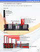
1-Getting Started 7. The MaxNAS R8 interface components The following figures illustrate the connector locations for the RAID subsystems.
1-Getting Started 8. Visual and Audible Indicators The MaxNAS R8 has an LCD panel, LEDs, and a buzzer to inform the user of the overall health and function of the unit. The following chart describes the various conditions indicated: Indicator Normal Status Problem Indication System Error LED Off Glows red to indicate system fault. Log into the management GUI for further information Blinks green when there is network activity on the LAN 1 port.
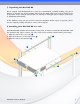
2-Connecting the MaxNAS R8 Chapter 2- Connecting the MaxNAS R8 1. Connect Your MaxNAS R8 Before you begin, please install your MaxNAS R8 in a properly ventilated rack (please see “Installing your MaxNAS in a rack, page 8) Step 1. Remove the disk canisters from the packing material and carefully insert into the MaxNAS R8. Step 2. Secure each canister into position and push the latch until it snaps into place. Step 3. Connect the provided power cords into the power sockets on the back panel.
2-Connecting the MaxNAS R8 2.1 Wizard Installation and Usage ! IMPORTANT! The setup wizard uses TCP port 10000 and UDP ports 11000-11001 For communication. If you are using a software firewall, please make sure to unblock those ports in order for the wizard to get access to the MaxNAS R8. 2.1.1 Macintosh OS X The wizard application for Mac OS X is located on your MaxNAS R8 CD in the “wizards” folder. You may launch the wizard directly from the CD, or you can copy it to your Applications directory.
2-Connecting the MaxNAS R8 2.1.3.3 You may change the password by entering a new “New Password” field, and re-enter the password (case sensitive) in the “Confirm Password” field. Click End to conclude the wizard session. 2.2 Launching the IP Storage Administration GUI, DHCP Environment ! Windows hosts can access the MaxNAS R8 via WINS.
2-Connecting the MaxNAS R8 3. LCD Operation The MaxNAS R8 is equipped with an LCD on the front for easy status display and setup. There are four buttons on the front panel to control the LCD functions: Up (▲), Down (▼), Enter (↵) and Escape (ESC) keys. The following table illustrates the keys on the front control panel: Icon ▲ ▼ ↵ ESC Function Up Button Down Button Enter Escape Description Select the previous configuration settings option. Select the next configuration settings option.
2-Connecting the MaxNAS R8 4. Adding External Disks The MaxNAS R8 has two rear USB ports, two front USB ports, and one eSATA port for attaching external storage devices such as the Fantom Drives G-Force Megadisk lines of products, formatted in FAT32 or NTFS. Please note that NTFS volumes will be available in read only mode. The MaxNAS R8 supports up to 6 external storage devices.
3-Administering the MaxNAS R8 Chapter 3- Administering the MaxNAS R8 This chapter describes the menu and control structure for your MaxNAS R8. The configuration is firmware-based and its operation is independent of host computer type or operating system. Connecting to the MaxNAS R8 web interface is as easy as typing its IP address or WINS name into the navigation bar of an Internet browser window. Once you have done so, you will be presented the initial login screen.
3-Administering the MaxNAS R8 To log in to the MaxNAS R8 administration interface, click “Admin” and enter the Administrator password. By default, the Administrator IMPORTANT! Only one administrator login password is “admin”. ! may be logged in to the web interface at a time. At initial login, the user will be greeted with the Product Information Screen: The administration user interface utilizes a paned desktop motif, and is organized in three sections: 1. The navigation pane (left) 2.
3-Administering the MaxNAS R8 The Main Menu Navigation Tree 1. System information 1.1 Product Information 1.2 System / Service Status 1.3 System Logs 2. System Management 2.1 Time Settings 2.2 System Notification Settings 2.3 Firmware Upgrade 2.4 Scheduled power on/off 2.5 UPS Settings 2.6 Wake on LAN settings 2.7 SNMP configuration 2.8 Utilities 2.8.1 Administrator Password 2.8.2 Configuration Management 2.8.3 Factory Restoration 2.8.4 Reboot & Shutdown 2.8.5 File System Check 3.
3-Administering the MaxNAS R8 1. System Information 1.1 System Information This page is the first page you see when you enter the MaxNAS R8 web interface. On this page you will see basic information about the RAID subsystem including the firmware version and the current uptime. 1.2 System and Services Status This page displays information about the current status of the MaxNAS R8 including CPU load, Fan Speed and the current status of each supported network service. 1.
3-Administering the MaxNAS R8 2. System Management The System Management Configuration menu contains basic system settings and configuration options. It is strongly suggested that you go through each of these menus at least once to ensure that you are taking advantage of everything the MaxNAS R8 has to offer. 2.1 Time This settings page is where you would go to set the date and time for your MaxNAS R8.
3-Administering the MaxNAS R8 2.5 UPS Settings The MaxNAS R8 will monitor and respond to UPS status messages from a compatible attached UPS (for a list of compatible devices see Appendix D). To use this feature you must first connect the UPS to the NAS via the serial port on the back of the NAS.
3-Administering the MaxNAS R8 2.8.4 Reboot & Shutdown You can reboot or shut down the MaxNAS R8 from this page. 2.8.5 File System Check This menu is where you go to initiate a file system check on the RAID system. Normally this is not required unless the RAID subsystem was shut down unexpectedly or otherwise disconnected without warning. 3. Network Configuration This Configuration menu contains settings and control panels for all of the network features of the MaxNAS R8.
3-Administering the MaxNAS R8 Jumbo Frame Support Jumbo frame support is a feature which allows Ethernet hardware to send, receive or transport Ethernet frames greater than the default 1518 bytes packet size (Also referred to as MTU). The MaxNAS R8 supports jumbo frames of up to 9000 bytes.
3-Administering the MaxNAS R8 3.2 LAN2 Configuration The LAN Configuration screen for the LAN2 (“LAN”) Interface allows for the following controls: The following table lists the menu items on the LAN2 (“LAN”) Configuration page: MAC Address This field displays the MAC address of the LAN port Jumbo Frame Support Like WAN, this port also supports Jumbo Frames. (For more information about Jumbo Frames see section 4.1.1) IP Address LAN2 port requires static addressing, and does not support DHCP.
3-Administering the MaxNAS R8 It is recommended that you disable services you will not require for security purposes. See Chapter 4 for details on how to use these technologies in Windows and Macintosh environments. 3.3.1 SMB/CIFS The Server Message Block network protocol is the most widely used network protocol. It is used by all variants of the Microsoft Windows operating system, Apple Macintosh OS X, and most Unix and Linux variants include support for it even if using a different networking protocol.
3-Administering the MaxNAS R8 FTP Use this option to enable or disable the FTP service on your MaxNAS R8. This setting is disabled by default. Secure FTP (Explicit) In some FTP environments it is a good idea to enable FTP security. Be sure that your FTP client also supports Secure FTP connectivity. Port Use this setting to define a port for your MaxNAS R8 FTP traffic. The default port is 21. FTP Encode If your FTP client or operating system does not support Unicode (e.g., WinME, MaxOS 9.
3-Administering the MaxNAS R8 MaxNAS R8 in the “Network Places” dialog on their computers. You may enable or disable UPNP support by navigating to “System Network” -> “UPnP.” Click Apply to complete the operation. 3.3.8 nSync/rSync Target Configuration The MaxNAS R8 supports remote synchronization through the nSync and Rsync target backup features.
3-Administering the MaxNAS R8 The column, “Status,” will display the most recent SMART reported health status for each disk mechanism. To view the SMART results, click on the smart status indication next to the specified disk mechanism, and the detailed information will appear. To manually trigger a SMART health test, click Test Note: Under normal circumstances manually running a SMART in the SMART Info window.
3-Administering the MaxNAS R8 The Create RAID window allows you to configure your MaxNAS R8 into a wide range of possible RAID configurations. Follow the steps below to create a new RAID system on the MaxNAS R8: 1. To begin the RAID creation process click the check box in the “Used” column for each of the drives you want to use as a part of the RAID system. When using a parity-based RAID configuration it is advisable to configure at least one drive as the hot spare for that RAID set.
3-Administering the MaxNAS R8 4.2.2 Expanding NAS volumes To expand the network accessible space of a RAIDset to take over unused space, select the on the RAID information screen (see above, section 4.2.) desired RAIDSet and click The RAID Configuration page will appear. Select the “Expand” tab in the tab bar (see illustration.) The Expand RAID Space screen will appear. Select the new percentage of the resulting volume to be used for network access. Remaining space may be allocated for iSCSI targets.
3-Administering the MaxNAS R8 4.2.4 Delete RAIDSet on the RAID information To edelete a RAIDset, select the desired RAIDSet and click screen (see above, section 4.2.) The RAID Configuration page will appear. Click Remove RAID and confirm the operation in the following confirmation dialog. 4.3 iSCSI Space Allocation The MaxNAS R8 has the ability to create special volumes for use via iSCSI.
3-Administering the MaxNAS R8 to discover the iqn of your new volume. In the Modify iSCSI Volume menu you can enable/ disable the volume, change the date, LUN ID number, enable/disable CHAP and/or change the user name and password. If there is an attached initiator, its IQN will be displayed. 4.3.3 Expanding an iSCSI volume The MaxNAS R8 has the ability to expand an existing iSCSI Target Volume into unused space . on the same RAID set.
3-Administering the MaxNAS R8 4.4 Shared Folder Management The Shared Folder Management menu lists all of your shared folders and contains controls for folder/share management, ZFS snapshots, NFS access controls and Samba user access rights. 4.4.1 Creating a new folder To create a new folder click . The Add Folder menu will appear. • Choose the RAID ID that corresponds to the RAID set that you want the folder to reside on. • Assign a name to the folder. • Optional: Assign a description to the folder.
3-Administering the MaxNAS R8 and then click . The NFS Config menu has two tabs, pictured below. The “NFS” tab lists every host for which you’ve assigned NFS access rights, as well as edit or remove host access rights. to control host access rights to the NFS share, select the “Add” tab. The following is a description of the access controls: • Put the host name or IP in the Host Name field. • Set Read Only or Writable privileges for that host.
3-Administering the MaxNAS R8 4.4.6 Access Control ACLs, or Access Control Lists are how you manage SMB/CIFS and FTP rights to your shared folders and sub-folders on the MaxNAS R8. To open the ACL menu, Note: ACLs cannot be click on a shared private folder (a folder that is not set to public) set for public folders and then click the ACL button.
3-Administering the MaxNAS R8 You must assign an export share name, and a share folder with the corresponding name will be created on the MaxNAS R8. You may also enter any additional information such as a description and set browsable and public share attributes IMPORTANT: The Export Share for the share (optional). Click Apply to mount the iSCSI Name for each new Stackable iSCSI volume must be unique. volume and create the export share. ! 4.5.
3-Administering the MaxNAS R8 4.6.1 Adding a new ISO image share To add a new ISO image share, select the sharepoint where the ISO image resides to launch the from the pulldown Mount Table window. In the Mount Table menu that appears you will see any valid *.iso files listed and the folder(s) within which they reside. Select the ISO you want to mount in the “Current Directory” list. Mounted ISOs will appear as a new folder in the shared folder that originally held the ISO file.
3-Administering the MaxNAS R8 5.2 Group Administration When providing shares to non Active Directory clients, the MaxNAS R8 provides its own user and group administration. Permissions and authorization for users and groups are assigned to each folder shared. To access group control please navigate to “Local Users and Groups” -> “Local” -> “Groups.” 5.2.1 Creating Groups in the Local To create a new group, click Group Configuration screen.
3-Administering the MaxNAS R8 5.3.1 Creating Local Users in the Local To create a new user, click User Configuration screen. In the following screen (illustrated right) enter the new user name and password, and assign to groups by selecting the desired groups from the “Group List” pane (right,) and click and drag them to the “Member List” pane (left.) to remove any users, selecting the desired users from the “Member List” pane (left,) click and drag them to the “Group List” pane (right.
3-Administering the MaxNAS R8 6. Application Service Controls The Application Server Configuration menu contains controls for managing the built in print server and the Digital Audio Access Protocol streaming media server (used primarily by Apple’s iTunes) 6.1 Print Server Management The MaxNAS R8 Can share a USB attached printer to your network. The Print Server page displays information about the USB printer for identification purpose.
3-Administering the MaxNAS R8 with Thecus modules, and you may wish to create your own or add other user created modules as well; There is a Thecus community with many various modules available at their website http://onbeat.dk/thecus. Please note that Micronet offers no support or endorsement for any content on this site. All installed modules will be listed in one of the two sections of the Module Menu. To access the module management, navigate to “System” -> “Module Management.
3-Administering the MaxNAS R8 8.1 Creating a backup Task To create a new nSync/rSync task click window will appear. on the nSync menu and the “Add nSync Task” The options in this menu are as follows: Task Name Target Server Type nSync Mode Target IP Share Folder Username/Password Test Connection Schedule This is the name your nSync/rSync task.
3-Administering the MaxNAS R8 8.2 Setting Up an Nsync Target on an Nsync Device In order for the target Nsync server to accept the Nsync backup job, please ensure that the following are conditions are met. Consult the target server device documentation for instructions: • Make sure that the Nsync server service is enabled. • A user account matching the username and password specified in the Nsync job • The user account has write access to the nsync folder.
4-Connecting Users Chapter 4- Connecting Users Once the MaxNAS R8 has been configured with storage, shares, users, groups, and permissions it is ready to accept user connections. The MaxNAS R8 supports SMB/CIFS network services as well as Webdisk/Secure Webdisk user connections. This chapter includes discussion on both of those services and connection methods. 1. SMB/CIFS User Access Configuration SMB shares are accessible from Windows 95 and newer, OS-X 10.
4-Connecting Users 1.2 Mapping a Network Drive (OS-X) The simplest method to locate and connect your MaxNAS R8 to an OS-X workstation is by using the Finder Network browser. If you can’t locate the computer or server within the network browser, you may be able to find it by typing its network address in the Connect to Server dialog, accessible from the “Go” -> “Connect to Server” Finder menu option.
4-Connecting Users 2. Using Webdisk The MaxNAS R8 provides a WebDisk function that allows you to access the system over the Internet from any browser. ! IMPORTANT: Make sure that WebDisk Support or Secure WebDisk Support is enabled in the Service Support screen in the system’s Network menu. Please see chapter 3, section 3.3.6 for more information 2.1 Logging In Note: Webdisk can operate normally (unsecured) The When initially logging in to secure webdisk, or in secured mode.
4-Connecting Users The WebDisk page will appear showing folders made currently available to you via the Access Control List (ACL) in the Folder item under Storage menu. Click on a folder name to enter the folder. The folder’s page will appear, displaying files and folders. 2.2 The Webdisk control interface The webdisk interface follows a traditional explorer multipane layout. The left pane displays the directory structure, and the right pane displays the files in the selected directory.
4-Connecting Users Download a file to your computer Upload file from your computer to the current directory. Change user password Logout Displays directories in the file browser pane Displays files matching the filter only. 3. Using the Photo Browser The MaxNAS R8 includes a fully functional Photo Server, which allows users to view, share photos, and even create their own albums right without any software required.
4-Connecting Users the “Add” button to upload pictures into the album. The Upload Photos screen will appear, as illustrated: Click Browse... to navigate and select the desired image to upload. In the respective entry boxes to the right, enter a short subject and description as desired. Up to 8 images can be uploaded at . a time. When all images were selected and the description fields entered, click 3.3 Deleting and Modifying Pictures in an Album “edit.
4-Connecting Users 4. Using iSCSI iSCSI allows two devices to negotiate and then exchange SCSI commands using IP networks. iSCSI takes a popular high-performance local storage bus and emulates it over wide-area networks, creating a storage area network (SAN). Unlike some SAN protocols, iSCSI requires no dedicated cabling; it can be run over existing switching and IP infrastructure. As a result, iSCSI is often seen as a low-cost alternative to Fibre Channel which requires dedicated infrastructure.
4-Connecting Users username and password. Click iSCSI Initiator properties window. OK to commit CHAP authentication, and OK on the Enable CHAP 4.1.5. Open the disk management console. A list of the attached drives and their respective volumes will appear. Each Volume set will appear as an individual disk in the management console. Upon the first time the MaxNAS R8 iSCSI volume is connected, an “Initialize and Convert Disk Wizard” should appear when the disk management console is run.
4-Connecting Users Full format. A Quick format will take just a few minutes but will do less verifying of the drive than a full format. Click Start. Once the format process is complete your iSCSI volume is ready to use. 4.2 OS-X >10.4.10 Host Setup The MaxNAS R8 has been tested and qualified for use with the GlobalSAN initiator from Studio Network Solutions. It can be obtained from their web site at http://www.studionetworksolutions. com.
4-Connecting Users 4.2.7 Select the new partition map type. 4.2.8 Select the desired file system format and volume name for each partition in the volume scheme (optional.) 4.2.9 Click 4.2.10 Click Options Apply . Select “Apple Partition Map” or “GUID” in the dialog box and click OK . . Your MaxNAS R8 iSCSI volume is ready to use! 3.2.6 3.2.7 3.2.8 3.2.6 3.2.9 MaxNAS Owner’s Manual 3.2.
4-Connecting Users 5. Connecting to MaxNAS R8 Attached Printers With a USB Printer attached, the MaxNAS R8 can offer central network printing to all your networked computers. ! IMPORTANT! Before you begin, please make sure the driver for your printer is properly installed on your computer. Please consult your printer manufacturer for up to date drivers for your host operating system 5.1 Windows XP SP2 To set up the Printer Server in Windows XP SP2, follow the steps below: 1.
4-Connecting Users 5.2.3 Select Add a network, wireless or Bluetooth printer. 5.2.4 Select The printer that I want isn’t listed. You can press The printer that I want isn’t listed to go into next page without waiting for Searching for available printers to finish. 5.2.5 Click Select a shared printer by name. In the address entry box, type http://:631/printers/usb-printer in the box, where is the IP address or Netbios name of the MaxNAS R8. Click Next .
4-Connecting Users 5.3 MacOS X The following instructions are based on printer installation on a Mac OS X 10.5 based host. Other Mac OS X hosts are configured similarly. 5.3.1 Access the printer control panel, located in System Preferences. 5.3.2 Click the in the “Print & Fax” control panel (illustrated right.) 5.3.
5-Understanding RAID Chapter 5- Understanding RAID The MaxNAS R8 controller subsystem is a high-performance SATA drive bus disk array controller. When properly configured, the RAID subsystem can provide non-stop service with a high degree of fault tolerance through the use of RAID technology and advanced array management features. The RAID subsystem can be configured to RAID levels 0, 1 (0+1), 5, and 6.
5-Understanding RAID RAID 1 (Disk Mirroring) RAID 1, also known as “disk mirroring”, distributes duplicate data simultaneously to pairs of disk drives. Pros: RAID 1 offers extremely high data reliability as all the data is redundant. If one drive fails, all data (and software applications) are preserved on the other drive. Read performance may be enhanced as the array controller can access both members of a mirrored pair in parallel.
5-Understanding RAID RAID 6 Also known as dual parity, RAID 6 is similar to RAID 5, but offers double the fault tolerance by performing two parity computations on overlapping subsets of the data. RAID 6 offers fault tolerance greater that RAID 1 or RAID 5 but only consumes the capacity of 2 disk drives for distributed parity data. RAID 6 is an extension of RAID 5 that uses a second independent distributed parity scheme.
6-Troubleshooting Chapter 6- Troubleshooting Daily Use Tips • Read this User’s Guide carefully. Follow the correct procedure when setting up the device. • Additional application software may have been included with your drive. Please review the documentation included with this software for information on the operation and support of this software. The documentation can usually be found in an electronic format on the included CD. • Always operate your drive on a steady, level surface.
6-Troubleshooting Resetting the MaxNAS R8 Should the MaxNAS R8 become inaccessible (blinking fault light, forgotten password) or if directed by MicroNet support, please follow the below procedure to reset the MaxNAS R8 to factory default: Using the front panel, press this sequence: 1. Press [↵] button 5 times 2. Press [▼] button 2 times 3. Press [↵] button 1 times 4. Press [▼] button 2 times 5. Press [↵] button 1 times the WAN IP will revert to default IP 192.168.1.
6-Troubleshooting Q: There is a fault light and/or the buzzer is beeping! A: Do not turn off or reset the unit! Follow these steps to identify and correct the alarm: 1. Refer to Chapter 1, Section 7 to identify the alert., and login to the MaxNAS R8 administration user interface. 2. Go to the System menu and choose Logs item. 3. The System Log screen appears. 4. Click the Error button and all recorded errors appear. The log entries will help you diagnose the problem.
A-Getting Help Appendix A: Getting Help If you experience problems with your MaxNAS R8, please contact your Authorized MicroNet Reseller for assistance. If the reseller is unable to resolve your issue, please contact MicroNet’s Help Desk for assistance. Please have the model, serial number, date of purchase, and reseller’s name available before making contact. If possible, call from a telephone near the system so we can direct you in any necessary system corrections.
B-RAID Level Comparison Table Appendix B: RAID Level Comparison Table RAID Level Span 0 1 10 5 6 Description Min. Max. Capacity Data Drives Drives Reliability Also known as disk spanning. Data 1 4 (N) No data protection is distributed sequentially to all Disks drives. There is no data protection. Also known as striping 1 4 (N) No data Data distributed across multiple Disks Protection drives in the array simultaneously.
C-Active Directory Appendix C: Active Directory With Windows 2000, Microsoft introduced Active Directory (ADS), which is a large database/ information store. Prior to Active Directory the Windows OS could not store additional information in its domain database. Active Directory also solved the problem of locating resources; which previously relied on Network Neighborhood, and was slow. Managing users and groups were among other issues Active Directory solved.
D- Support UPS List Appendix D: Supported UPS List The MaxNAS R8 can support UPS communication with the following UPS communication protocols: SEC protocol Generic RUPS model Generic RUPS 2000 (Megatec M2501 cable) PhoenixTec protocol Safenet software The following Models have been tested and approved for compatibility: Brand Series Ablerex MS-RT ActivePower 1400VA AEC Model Notes MiniGuard UPS 700 M2501 cable Back-UPS Pro Matrix-UPS Smart-UPS APC Back-UPS 940-0095A/C cables, 940-0020B/C cables
D- Support UPS List Brand Series Model Notes PowerPal P-series Fenton Technologies PowerPal L-series PowerOn PowerPure Fairstone Fideltronik Fiskars L525/L625/L750 Ares 700 and larger Other Ares models PowerRite MAX PowerServer 10, 30 All models with alarm interface MP110/210 Gamatronic MS-T MS µPS3/1 Gemini HP UPS625/UPS1000 R3000 XR R5500 XR INELT Monolith 1000LT Infosec iPEL Ippon (various) Liebert UPStation GXT2 contact-closure cable Masterguard Meta System 350, 500, 750, 1000 (v
D- Support UPS List Brand Orvaldi Series Model Notes various not 400 or 600 SMK-800A Powercom Powercom ULT-1000 TrustTrust 425/625 BNT-1000AP Advice Partner/King Pr750 BNT-2000AP PowerGuard PowerKinetics PowerTech Power Walker PG-600 9001 Comp1000 DTR cable power Line-Interactive VI1000 Powerware Powerwell PM525A/-625A/-800A/-1000A/-1250A 3110, 3115, 5119, 5125, 5119 RM, PW5115 PW5125PW9120, PW9125, 9120, 9150, 9305 RPF525/625/800/1000 Repotec RPT-800A RPT-162A SMS (Brazil) SOLA SOLA/BASIC Mex
E-Glossary Appendix E: Glossary Active Directory an implementation of LDAP directory services by Microsoft for use in Windows environments. Active Directory allows administrators to assign enterprise wide policies, deploy programs to many computers, and apply critical updates to an entire organization. An Active Directory stores information and settings relating to an organization in a central, organized, accessible database.
E-Glossary Disk Array A Disk Array is a logical disk comprised of multiple physical hard disks. The number of hard disks in an disk array is dictated by the type of the array and the number of spares that may be assigned to it. Furthermore, whether a disk array can be built using part of the space on a disk (as opposed to being forced to use the whole disk) depends upon the implementation. Disk Arrays are typically used to provide data redundancy and/or enhanced I/O performance.
E-Glossary by any RAID array as a backup. In the event a hard disk in a RAID array fails, this backup is automatically mobilized by the RAID controller to step in place of the failed hard disk. The data in the failed hard disk is “reconstructed” and written into the new hard disk. In the case of a RAID 1, data is reconstructed by simply copying the contents of the surviving disk into the spare.
E-Glossary be obtained by simply evaluating the XOR of the N bytes. Parity allows one error in a group (of bytes) to be corrected. Partition The space contributed to each array on a physical drive is referred to as a partition. PCI An acronym for “Peripheral Component Interconnect”. It is Intel’s local bus standard that supports up to four plug-in PCI cards per bus. Since PCs can have two or more PCI buses, the number of PCI cards they can support are a multiple of four.
E-Glossary of the disks fails, its contents can be retrieved from the duplicate disk. Furthermore, a RAID 1 array can also improve the throughput of read operations by allowing separate reads to be performed concurrently on the two disks. RAID 5 A RAID 5 array is similar to a RAID 4 array in that, it utilizes a striped set of three or more disks with parity of the strips (or chunks) comprising a stripe being assigned to the disks in the set in a round robin fashion.
E-Glossary Secondary Storage Mass storage devices such as hard disks, magneto-optical disks, floppy disks and tapes are frequently referred to as secondary storage. Secure Sockets Layer (SSL) is a cryptographic protocol which provide secure communications on the Internet. SSL provides endpoint authentication and communications privacy over the Internet using cryptography. In typical use, only the server is authenticated (i.e.
E-Glossary the favoured replication model is the HUB and SPOKE, and thus the WINS design is not central but distributed, each WINS server holds a full copy of every other related WINS system records. There is no hierarchy in WINS (unlike DNS) but like DNS its database can be queried for the address to contact rather than broadcasting a request for which address to contact. The system therefore reduces broadcast traffic on the network, however replication traffic can add to WAN / LAN traffic.
F-Product Specifications Appendix F: Product Specifications System Architecture CPU: System RAM: NVRAM: Disk Interface: Network Interface: Expansion Ports: System Displays: Disk Mechanisms: Intel® Core2® Architecture, 1.86GHz 1GB DDR On-board non volatile memory for firmware 8 channel SATA2-300 with NCQ drive controller Dual Gigabit Ethernet host controllers 3x USB 2.0 Type A Ports for external disk and printer hosting 1x eSATA port for external disk hosting 1x USB 2.
F-Product Specifications System Features RAID level 0, 1, 5, 6, 10 and Span configurations Multiple RAID and LUN support Automatically and transparently rebuilds hot spare drives Hot swappable, lockable disk drive modules Disk S.M.A.R.T.
G-Licence and Copyright Appendix G: Licence and Copyright This product included copyrighted third-party software licensed under the terms of GNU General Public License. Please see THE GNU General Public License for extra terms and conditions of this license. Source Code Availability Micronet has exposed the full source code of the GPL licensed software. For more information on how you can obtain our source code, please visit http://www.micronet.
G-Licence and Copyright GNU General Public License Version 2, June 1991 Copyright © 1989, 1991 Free Software Foundation, Inc. 51 Franklin St, Fifth Floor, Boston, MA 02110-1301 USA Everyone is permitted to copy and distribute verbatim copies of this license document, but changing it is not allowed. PREAMBLE The licenses for most software are designed to take away your freedom to share and change it.
G-Licence and Copyright contents constitute a work based on the Program (independent of having been made by running the Program). Whether that is true depends on what the Program does. 1.
G-Licence and Copyright code or executable form with such an offer, in accord with Subsection b above.) The source code for a work means the preferred form of the work for making modifications to it. For an executable work, complete source code means all the source code for all modules it contains, plus any associated interface definition files, plus the scripts used to control compilation and installation of the executable.
G-Licence and Copyright 9. The Free Software Foundation may publish revised and/or new versions of the General Public License from time to time. Such new versions will be similar in spirit to the present version, but may differ in detail to address new problems or concerns. Each version is given a distinguishing version number.
MicroNet Techology 20525 Manhattan Place Torrance, CA 90501 www.MicroNet.com 02-08-2010 Rev 2 The material in this document is for information only and is subject to change without notice. While reasonable efforts have been made in the preparation of this document to assure its accuracy, MicroNet Technology assumes no liability resulting from errors or omissions in this document, or from the use of the information contained herein.