User’s Manual Wireless LAN Outdoor Bridge Model No.: SP915G http://www.micronet.
Table of Contents Table of Contents...........................................................................................2 Package Contents..........................................................................................4 Hardware Setup..............................................................................................4 Ethernet & RS-232 Console Connector: ............................................................. 4 PSE BOX : for Power Over Ethernet (POE)..........................
Bridge and Bridge ........................................................................................................... 22 DHCP Server Setting Æ DHCP ....................................................................23 WAN Setting Æ WAN..................................................................................25 WAN Status Æ WAN Status .........................................................................26 Admin setting Æ Admin ............................................................
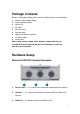
Package Contents Before installing the product, please verify the following items in the package: z z z z z z z z z Wireless LAN Outdoor Bridge Quick installation guide Manual CD RF cable Ethernet cable Console cable Power-over-Ethernet injector AC Power cable Accessories Note: Using a power supply with a different voltage than the one included with the Outdoor Bridge will cause damage and void the warranty for this product. Hardware Setup Ethernet & RS-232 Console Connector: 1.
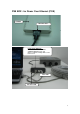
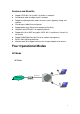
PSE BOX : for Power Over Ethernet (POE) PSE BOX AC Power cable Power Over Ethernet : RJ-45 cable connecter PSE BOX (POWER &DATA OUT port) and Wireless-G Outdoor Bridge WAN or LAN Ethernet Port Power LED Link Active LED 5
Minimum System Requirements z z Computers with Windows, Macintosh, or Linux-based operating systems with an installed Ethernet Adapter Internet Explorer version 6.0 or Netscape Navigator version 7.0 and above Introduction The SP915G Outdoor Bridge covers a long operating distance, providing an 802.11b/g outdoor WLAN which enables users to access the Internet or an organization’s network.
Features and Benefits z z z z z z z z z z Support IEEE 802.11b and 802.11g wireless standards Provide dual radio to bridge wireless networks Support multiple operation modes for access point, gateway, bridge and repeater Provide up to 100mW transmit power Support power over Ethernet for deployment flexibility Compliant with IEEE 802.11d regulatory domain Support 64/128-bit WEP encryption, WPA, 802.
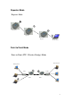
Repeater Mode Repeater Mode Access Point Repeater1 Repeater2 Wireless Client Point to Point Mode Point to Point (P2P : Wireless Bridge) Mode Wired Network Wired Network LAN2 LAN1 L2 Switch L2 Switch P2P-1 P2P-2 8
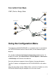
Point to Multi Point Mode PMP ( Wireless Bridge) Mode Wired Network LAN2 L2 Switch Wired Network P2P-1 LAN1 Wired Network PMP LAN3 P2P-2 L2 Switch Using the Configuration Menu To configure the OUTDOOR BRIDGE, use a computer which is connected to the OUTDOOR BRIDGE with an Ethernet cable (see the Network Layout diagram). First, disable the Access the Internet using a proxy server function.
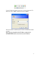
A screen will pop up and request you to enter user name and password. The default user name is “admin”, the default password is “default” After the connection is established, you will see the user identification window as shown. Note: If you have changed the default IP address assigned to the OUTDOOR BRIDGE, make sure to enter the correct IP address.
Device IP Setting Æ Ethernet LAN is short for Local Area Network. This is considered your internal network. These are the IP settings of the LAN interface for the OUTDOOR BRIDGE. These settings may be referred to as private settings. You may change the LAN IP address if needed. IP address: The default IP address is 192.168.2.254. Assign a static IP address that is within the IP address range of your network. IP netmask: Enter the subnet mask. All devices in the network must share the same subnet mask..
AP Setting --> Wireless0 or Wireless1 13
Mode: AP/Bridge or Disable Wireless. Select AP/Bridge if you want to set wireless in AP mode. Speed: The speed are Auto, 1Mbps, 2Mbps, 5.5Mbps, 6Mbps, 9Mbps,11Mbps, 12Mbps, 18Mbps, 24Mbps, 36Mbps, 48Mbps, 54Mbps. Channel: You can select 1 of 3 country setting (US: Channel 1 ~ 11, ETSI: Channel 1 ~13, Japan: Channel 1 ~ 14 )(Note: Channel 14 only 802.11b mode). All devices on the network must share the same channel. (Note: The wireless adapters will automatically scan and match the wireless setting.
the devices in your network when using the 802.1x feature. WPA (Wi-Fi Protected Access) authorizes and identifies users based on a secret key that changes automatically at regular intervals. WPA uses TKIP (Temporal Key Integrity Protocol) to change the temporal key every 10,000 packets (a packet is a kind of message transmitted over a network.) This ensures much greater security than the standard WEP security.
password 26 bit HEX code.( Note :Currently version does not support ASIC code.) Valid Key: Select one of the keys in the Key table to be the active key. Key Table: Enter up to four encryption keys here. Set Encryption to Open System/Shared Key WEP auth method: Select Open System and Shared Key to communicate the key across the network. WEP mode: Select 64, 128 bits. Key Type: 64 bit support WEP password 10 bit HEX(Hexadecimal digits consist or the numbers 0-9 and the letters A-F) code.
to restore previous value. To make settings working click Submit-> Reset-> Restart.) Point to Point Mode Setting Æ Wireless0 or Wireless1 Point to Point (P2P : Wireless Bridge) Mode Wired Network Wired Network LAN2 LAN1 L2 Switch L2 Switch P2P-1 P2P-2 PtP mode setting is like AP mode setting, but encryption only WEP encryption method can select.
Wireless1.Set WEP encryption the same as P2P-1 Wireless1.Dsiable P2P-2 Wireless1 WPA encryption. Pull down select “y” in hidden SSID to disable SSID broadcast. Point to Multi Point Mode Setting Æ Wireless0 or Wireless1 PMP ( Wireless Bridge) Mode Wired Network LAN2 L2 Switch Wired Network P2P-1 LAN1 Wired Network PMP LAN3 P2P-2 L2 Switch PtMP mode setting is like AP mode setting, but encryption only WEP encryption method can select.
00.01.02.03.04.08 and P2P-2 Wireless1 Mac: 00.01.02.03.04.0A in WDS macs fields. Then set WEP encryption, and disable WPA encryption. Pull down select “y” in hidden SSID to disable SSID broadcast. Set P2P-1 Wireless1 in AP/Bridege Mode, and type PMP Wireless1 Mac: 00.01.02.03.04.06 in WDS macs fields. Then set channel the same as PMP Wireless1.Set WEP encryption the same as PMP Wireless1.Dsiable P2P-1 Wireless1 WPA encryption. Pull down select “y” in hidden SSID to disable SSID broadcast.
Repeater Mode Setting Æ Wireless0 or Wireless1 Repeater Mode Access Point Repeater1 Repeater2 Wireless Client Repeater mode setting is like AP mode setting, but encryption only WEP encryption method can select. e.g AP Wireless0 Mac: 00.01.02.03.04.05 Wireless1 Mac: 00.01.02.03.04.06 Repeater1 Wireless0 Mac: 00.01.02.03.04.07 Wireless1 Mac: 00.01.02.03.04.08 Repeater2 Wireless0 Mac: 00.01.02.03.04.09 Wireless1 Mac: 00.01.02.03.04.
Mac: 00.01.02.03.04.08 in WDS macs fields. Then set channel the same as Repeater1 Wireless1.Set WEP encryption the same as AP Wireless1.Dsiable Repeater2 Wireless0 WPA encryption. Dual Radio Setting For Simultaneous Operation AP and Bridge e.g. Wireless0 do AP Setting as page 11 and Wireless1 do Bridge setting as page 17 (PtP Setting) or page 18 (PtMP setting).
DHCP Server Setting Æ DHCP 23
DHCP Server Control: Dynamic Host Configuration Protocol assigns dynamic IP addresses to devices on the network. This protocol simplifies network management and allows new wireless devices to receive IP addresses automatically without the need to manually assign new IP addresses. Select Subnet on device IP(Such as 192.168.2.254) to allow the OUTDOOR BRIDGE to function as a DHCP server. start IP: Input the first IP address available for assignment in your network.
WAN Setting Æ WAN 25
To select the connection type for WAN PORT, you can choose any of the following Mode: • For static IP, please click Static IP and type IP address, IP netmask, IP gateway. • For dynamic IP address, please click the Dynamic IP and type Hostname • For xDSL and using PPPoE to connect to Internet, please click PPPoE and type username and password. • For Disable WAN Port, please click Disable. (Note: If you change any item, click “submit” to store the value. Or click “clear” to restore previous value.
connect your ISP at PPPoE setting.
You can change login password (default password is “default”), SNMP user name and password, and SNMP Trap setting here. (Note: If you change any item, click “submit” to store the value. Or click “clear” to restore previous value. To make settings working click Submit-> Reset-> Restart.
Firewall setting Æ Firewall 29
In Firewall IP Rules fields you can define 20 IP rules to deny or pass networking which fit the rules. In Firewall MAC Rules fields you can control 20 MACs which can pass connect to system or deny from system. (Note: If you change any item, click “submit” to store the value. Or click “clear” to restore previous value. To make settings working click Submit-> Reset-> Restart.
Virtual Server setting Æ Virtual Server You can define 10 groups Virtual Server here. e.g. If you build a Server at local PC(client) and Wireless-G Outdoor AP/Bridge is connect to internet have a real IP. Check Enable the rule in Virtual Server and type Description, then key-in local PC’s IP in Local IP fields and port(use by the Server) in Local Port and select protocol (use by the Server). After finish those setting click Submit-> Reset-> Restart restart system to make settings work.
Connection Status It will show the device connection status.
Firmware upgrade Æ Upgrade Step 1 : Set your PC IP (192.168.2.X), and close PC’s firewall. Step 2 : Open a TFTP server on your PC and put the firmware in the same direct. Step 3 : Click on the Upgrade tab and then the main screen enter the PC IP address in the “tftp server :”field section 192.168.2.X , and the second option “file name” please key in the firmware file name. Then click Download and reset. It may take up to 2 minutes for the upgrade to complete.
Reset System Æ Reset Click Reset Æ Restart will store settings and restart system.
Specifications Standards Ethernet: Wireless: IEEE 802.3 / IEEE 802.3u IEEE802.11 b /g compliant Data Rate 54/48/36/24/18/12/11/5.5/2/1Mbps auto fallback Security 64/128-bit WEP Data Encryption, WPA, 802.1x and Access Control List Frequency Band 2.400~2.4835GHz (Industrial Scientific Medical Band) Interface 10/100BASE-TX auto-negotiation RJ-45 port x 2, Auto MDI/MDI-X RS-232 serial port N-Type Connector x 2 Transmit Power 20dBm (Typical) Operation Channel 11/N.