User’s Manual 8-Port VDSL Managed Switch Model No.: SP3508A http://www.micronet.
Table of Contents Chapter 1 Introduction ..................................................................................................1 1.1 Package Contents ..............................................................................................1 1.2 Key Features ......................................................................................................1 Chapter 2 Installation ....................................................................................................3 2.
5.7.2 Aggregator Information..........................................................................21 5.7.3 State Activity .........................................................................................21 5.8 Filter Database .................................................................................................22 5.8.1 IGMP Snooping .....................................................................................22 5.8.2 Static MAC Address .........................................
Chapter 1 Introduction Micronet SP3508A is an EoVDSL (Ethernet over VDSL) clustering switch that aggregates 8 VDSL lines into 2 Gigabit Ethernet uplinks. It delivers costeffective and high-performance broadband / multimedia services to multiunit building environments, such as enterprise, campus, hospital, hotel, and telecom. With QAM-based 4-band VDSL technology, the VDSL solution dramatically extends Ethernet and supports 5M/15M/25Mbps symmetrical bandwidth over existing telephone-grade wiring up to 1.
y y y Supports SNMP v1 RFC-1493 Bridge MIBs ¾ RFC-1643 Ethernet MIB ¾ RFC-1213 MIB II ¾ Enterprise MIBs ¾ RMON groups 1(Statistics), 2(Alarm), 3(Event), 9(History) Supports TFTP/XMODEM for firmware upgrade Built-in POTS/ISDN splitter for POTS/ISDN telephone service 2
Chapter 2 Installation 2.1 Hardware Installation This section describes how to install the switch and establish network connections. Users may install the user on any level surface. However, please take note of the following minimum site requirements. 2.
y 24-26 Gauge phone VDSL Port (RJ-11) 2.4 y y y y y y y y y wiring y Do not recommend 28 or above Gauge y 5M/5M: 1.7 km y 15M/15M: 1.1km y 25M/25M: 600m Connecting to Gigabit Ethernet The IP DSLAM has 2 X 10/100/1000 Mbps Giga Ethernet ports. Support full or half-duplex operation and transmission mode is using auto-negotiation. All network devices connected to the switch must support autonegotiation. Devices without auto-negotiation will operate at halfduplex.
2.5 y y y y y Connecting to RJ-11 Please ensure suitable VDSL Modem (SP3501AS) is installed before making a connection to any of the IP DSLAM (1-8) station ports. Users need to prepare 18 ~ 26 gauge one twist pair phone Line wiring with RJ-11 plugs at both ends. The Modem’s RJ-11 ports are easy-to-use and do not require installation of additional wiring. Every RJ-11 modular phone jack in the home can become a port on the LAN.
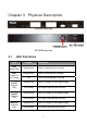
Chapter 3 Physical Description SP3508A front view SP3508A rear view 3.1 LED Definition LED Status PWR (Power LED) Steady/Green Device is powering on or reset ok. POST (Power On Self Testing) Steady/Green Lights on when device is booting. Off Turns off when booting is finished. 10/ACT (Ethernet LED) Steady/Green Flash/Green 100/ACT (Ethernet LED) Steady/Green 1000/ACT (Ethernet LED) Steady/Green Flash/Green Flash/Green Operation Lights up steadily to show good linkage.
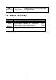
LINK (VDSL LED) 3.2 Steady/Green Each VDSL port has a LED and lights up to show good linkage. Switch Connectors Connectors Description Type VDSL Connecting to the VDSL Modem via a RJ-11 cable RJ-11 POTS Connecting to the telephone, Fax or ISDN modem RJ-11 Connecting to an Ethernet network device. RJ-45 Gigabit Ethernet Console AC Console port for managing the switch.
Chapter 4 IP Address Configuration 4.1 Out-Band Access 4.1.1 Console Port Users can configure the product with the local serial console port. The procedure is to connect a notebook computer to the RS-232 port, then boot windows @95/98/ME/2000 system, and run “Hyper-terminal” program into terminal window. Steps are as follows: Step 1. Set the parameters of connection according to below details.
Step 2. Connects PC with the IP DSLAM, the login window will appear on the screen. Enter the default login details: z Login: admin z Password: 123 The program will enter the following text-based user interface. Step 3. Choose ‘VDSL Switch Static Configuration’ to enter the page below.
Step 4. Choose ‘Administration Configuration’ to proceed to the page below. Step 5. Choose ‘IP Configuration’ to proceed to IP configuration page. Parameter Description Edit Select to change IP address, subnet mask and gateway. CTRL+A Action menu. Save Save changes and return back to ‘Device Configuration’ page. Previous Menu Quit the current page. Main Menu Return to the initial ‘Main Menu’ page.
4.2 Remote Access Users must setup the IP address with the local serial console port (RS-232 Port), and then use this IP address to control this VDSL switch via Telnet or Web-Based UI. Otherwise, users can change the computer’s IP domain to be the same as VDSL switch. Then use the default IP address to control this VDSL switch. 4.2.1 Telnet To enter Telnet, type the IP address of the switch to connect to management system. Type the default username and password.
Enter the default IP address of the switch into the web browser for the login confirmation window to appear.
Chapter 5 Web-Based UI Management Interface 5.1 Home Page This is the VDSL switch’s home page. The switch’s image on the top indicates which port is being connected. Pressing the ports on the image will open up a window to show port statistics. 5.2 Port Status This interface allows user to view port status.
Parameter Description State Display port status with either disable or enable. Link Status ‘Down’ is no link and ‘Up’ is link. Auto Negotiation VDSL Switch’ auto-negotiation mode. Speed status Port 9-10 are 10/100/1000Mbps and port 1- 8 are 5/15/25Mbps. Duplex status Display full-duplex or half-duplex mode. Flow control: Display flow control status with either enabled or disabled mode. Configure Display the state of user setup. Actual Display the negotiation result. 5.
5.4 IP Address User can configure the IP Settings in the interface below. This interface is accessible on the menu to the left of the browser. 5.5 Parameter Description IP Address Default: 192.168.16.250 Subnet Mask Default: 255.255.255.0 Gateway Default: 192.168.16.1 Switch Setting 5.5.1 Basic This is interface displays the basic information of the VDSL Switch such as firmware version, hardware version and MAC address.
Parameter Description Description Displays the name of the device. MAC Address The unique hardware address assigned by manufacturer. Firmware Version Displays the switch’s firmware version. Hardware Version Default config value version Displays the switch’s hardware version. Displays write to default EEPROM value tale version. 5.5.2 Advanced The interface allow advance configuration of the VDSL Switch.
Broadcast Storm Filter To configure broadcast storm control, enable it and set the upper threshold for individual ports. The threshold is the percentage of the port's total bandwidth used by broadcast traffic. When broadcast traffic for a port rises above the threshold set, broadcast storm control becomes active. Range: 5%, 10%, 15%, 20%, 25% and off. Priority Queue Service Settings Parameter Description First Come First Service The sequence of packets sent is depend on arrive order.
Protocol Enable Setting Parameter Description Enable Spanning Tree Allow STP to be enabled. Protocol Recommended setting is ‘enable’. Enable Internet Group Allow IGMP to be enabled. Multicast Protocol VLAN Protocol Allow selection of VLAN types. GVRP allows automatic VLAN configuration between the VDSL Switch and nodes.
5.6 Port Controls This section shows user how to change every port status and speed mode. The procedure that the VDSL Switch determines speed is as follows: 1. Confirm the phone cable have been connected with SP3508A and SP3501AS. 2. Power on both devices. 3. The device will start auto-speed function after SP3501AS re-boot. 4. SP3508A will try 25M mode to link with SP3501AS, if fail, auto speed down to 15M mode and re-link with SP3501AS.
5.7 Link Aggregation The Link Aggregation Control Protocol (LACP) provides a standardized means for exchanging information between Partner Systems on a link to allow their Link Aggregation Control instances to reach agreement on the identity of the Link Aggregation Group. It moves the link to that Link Aggregation Group, and enables its transmission and reception functions in an orderly manner.
LACP If enable, the group is LACP static trunking group. If disable, the group is local static trunking group. All ports support LACP dynamic trunking group. If connecting to the device that also supports LACP, the LACP dynamic trunking group will be created automatically. If LACP enable, users can configure LACP Active/Passive status in each ports Work Ports The max number of ports can be aggregated at the same time.
Parameter Description Active The port automatically sends LACP protocol packets. Passive The port does not automatically sends LACP protocol packets, and responds only if it receives LACP protocol packets from the opposite device. 5.8 Filter Database The Internet Group Management Protocol (IGMP) is an internal protocol of the Internet Protocol (IP) suite. IP manages multicast traffic by using VDSL Switch, routers, and hosts that support IGMP.
2. Report: A message sent by a host to the queries to indicate that the host wants to be or is a member of a given group indicated in the report message. 3. Leave Group: A message sent by a host to the queries to indicate that the host has quit the membership of a specific multicast group. 5.8.2 Static MAC Address When users add a static MAC address, it remains in the SP3508A’s address table, regardless of whether the device is physically connected to the switch.
5.8.3 Port Security A port in security mode will be “locked” without permission of address learning. Only the incoming packets with SMAC already existing in the address table can be forwarded normally. User can disable the port from learning any new MAC addresses, then use the static MAC addresses screen to define a list of MAC addresses that can use the secure port. Enter the settings, and then click to apply the changes on this page. 5.8.
5.9 VLAN Configuration A Virtual LAN (VLAN) is a logical network grouping that limits the broadcast domain. It allows user to isolate network traffic so only members of the VLAN receive traffic from the same VLAN members. Basically, creating a VLAN from a SP3508A is logically equivalent of reconnecting a group of network devices to another Layer 2 switch. However, all the network devices are still plug into the same SP3508A physically.
Support Protocol-based VLAN In order for an end station to send packets to different VLAN, it has to be either capable of tagging packets with VLAN tags or attached to a VLANaware bridge that is capable of classifying and tagging the packet with different VLAN ID based on not only default PVID but also other information about the packet, such as the protocol.
5.9.2 Port VID The interface sets the Port VLAN ID that will be assigned to untagged traffic on a given port. For example, if port 10's Default PVID is 100, all untagged packets on port 10 will belong to VLAN 100. The default setting for all ports is VID 1. This feature is useful for accommodating devices that you want to participate in the VLAN but that don't support tagging. Only one untagged VLAN is allowed per port.
5.10 Spanning Tree The Spanning-Tree Protocol (STP) is a standardized method (IEEE 802.1D) for avoiding loops in SP3508A networks. When STP enabled, ensure that only one path at a time is active between any two nodes on the network. It is recommended that users enable STP on all SP3508A to ensure a single active path on the network. 1. User can view spanning tree information about the Root Bridge in the following screen. 2. Users can view the spanning tree status of the SP3508A in the following screen.
Parameter Description Priority Users can change priority value to identify the root bridge. The bridge with the lowest value has the highest priority and is selected as the root. Range: 1~65535. Max Age Users can change Max Age value, the number of seconds a bridge waits without receiving. Spanning-Tree Protocol configuration messages before attempting a reconfiguration. Range: 6~40.
Parameter Description Port Priority Users can make it more or less likely to become the root port. The lowest number has the highest priority. If users change the value, it is necessary to reboot the SP3508A. Range: 0~255. Default: 128. Path Cost Specifies the path cost of the port that the SP3508A uses to determine which port are the forwarding ports. The lowest number is forwarding ports. If users change the value, it is necessary to reboot the SP3508A.
Parameter Description Roving Analysis State Enable or disable the port sniffer function. Analysis Port Analysis port can be used to see all monitor port traffic. Users can connect sniffer port to LAN Analysis, Session Wall or Netxray. Monitor Ports The ports for monitoring. All monitor port traffic will be copied to sniffer port. Users can select max 9 monitor ports in the SP3508A. If users want to disable the function, select monitor port to none. Monitor Rx Monitored receive frames from the port.
location, and contact person for the SP3508A. Fill in the system options data, and then click to update the changes on this page. Parameter Description Name Enter a name to be used for the SP3508A. Location Enter the location of the SP3508A. Contact Enter the name of a person or organization. 2. Community strings serve as passwords and can be entered as one of the following. Parameter Description Read only Enables requests accompanied by this string to display MIB-object information.
Parameter Description ‘Temperature Alarm’ trap When VDSL Switch’s internal temperature is greater than 70℃, system will send a “Temperature alarm" trap. ‘Fan Speed Alarm’ trap When the VDSL Switch’s internal cooling FAN doesn’t run, the system will send a “FAN speed alarm” trap. 5.13 Signal to Noise Ratio The following information provides a view of the current VDSL Attenuation value of the unit. 5.14 Security Manager This interface allows users to change the username and password.
Parameter Description Username This field provides the users to enter the desired username. Default: admin Assign/Change Allow users to enter the desired password. Password Default: 123 Reconfirm Password Re-enter the password in this section for verification. 5.15 TFTP Update Firmware The following menu options provide some system control functions to allow a user to update firmware and remote boot SP3508A’s system 1. Install TFTP Turbo98 and execution. 2. Copy firmware update version image.
5.16 Configuration Backup 5.16.1 TFTP Restore Configuration Use this page to set TFTP server address. Users can restore EEPROM value from here, however it is necessary to enter image in TFTP server and the SP3508A will download back the flash image. 5.16.2 TFTP Backup Configuration Use this page to set TFTP server IP address. Users can save current EEPROM value from here, then go to the TFTP restore configuration page to restore the EEPROM value.
5.17 Reset and Rebooting System These two interfaces allow users to reset and reboot the system. Parameter Description Reset The interface will reset the device back to factory default settings. Please ensure SP3508A is detached from the VDSL modem when performing this function. Reboot This interface allows user to restart the device with settings remaining unaltered.
Chapter 6 Application The VDSL provides home network architecture. Transforming an apartment into a Multiple-Family Home network area and sharing a single internet account for multiple users via Router & Cable Modem. It can provide unlimited access time in the internet at a reasonable low price. Bridging Functions The SP3508A provides full transparent bridging function. It automatically connects node addresses that are later used to filter and forward all traffic based on the destination address.
Chapter 7 Appendix 7.1 Appendix A: Specifications Model SP3508A Standards Interface IEEE802.3 10BASE-T, IEEE802.3u 100BASE-TX, and IEEE802.3ab 1000BASE-T standards z z z MAC Address Table Flow Control Distance 8k Entries z IEEE802.
Dimension Certification 435 x 255 x 44mm CE, FCC, RoHS 39
7.2 Appendix B: Troubleshooting z z Symptom: Power indictor does not light up (Green). ¾ Causes: Defective external power supply. ¾ Solution: Check the power plug by attaching with a functioning one. Check the power cord with other devices. If both tests fail, have the power supply replaced by qualified distributor. Symptom: Link indicator does not light up (Green). ¾ Causes: Network interface, network cable or switch port may be faulty. ¾ Solution: Power off and reconnect the VDSL switch.
7.3 Appendix C: System Diagnostics 7.3.1 Power and Cooling Problems If the POWER indicator does not turn on when the power cord is plugged in, users may have a problem with the power outlet, power cord, or internal power supply as explained in the previous section. However, if the unit should turn itself off after running for a while, check for loose power connections, power loss or surges at the power outlet, and verify that the fan on back of the unit is unobstructed and running prior to shutdown.
7.3.4 Cabling 1. Verify that the cable type is correct. Be sure RJ-45 cable connectors are securely seated in the required ports. Use 100Ω straight-through cables for all standard connections. 2. Use Category 5 cable for 100/1000Mbps Fast Ethernet connections, or Category 3, 4 or 5 cables for standard 10Mbps Ethernet connections. 3. Be sure RJ-11 phone wiring uses 18~26 gauge. 4. Make sure all devices are connected to the network. 5.
7.
7.5 Appendix E: Example of VLAN Setting 7.5.1 Port-Based VLAN Setting 1. Web management Æ Administrator Æ SP3508AS settings Æ Advanced: Protocol Enable SettingÆ VLAN Operation Mode: Select “Port-Based”. 2. Web management Æ Administrator ÆSP3508AS settingsÆVLAN Configuration.
3. Add VLAN Group 1, member: port 1 and port 9. 7.5.2 Tag-Based (IEEE 802.1Q) VLAN Setting 1. Web management Æ Administrator Æ SP3508A settings Æ Advanced: Protocol Enable SettingÆ VLAN Operation Mode: Select “802.1Q without GVRP”. 2. Administrator Æ VLAN Configuration: Select “Port VID” in this stage, users can define each port’s PVID and set traffic rules for each port.
3. VLAN Configuration: Select “Basic”. Highlight default_1 and click button to add/remove each port. 4. In default_1 group, add in or remove group members.
5. Click button to set Tag or Untag for each assigned port. 6. Click button to create new group.
7. Fill in new group name into VLAN Name. Set the VID number. Add in new group members. Click button. 8. Set Tag or Untag for group members and click button.
9. New group has been created, now users can highlight each group and click or button to modify or delete VLAN Group.