
Switch User Manual
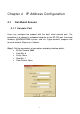
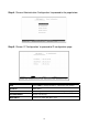
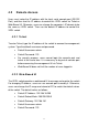
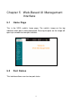
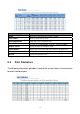
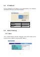
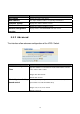
Table Of Contents
- Chapter 1 Introduction
- 1.1 Package Contents
- 1.2 Key Features
- Chapter 2 Installation
- Chapter 3 Physical Description
- Chapter 4 IP Address Configuration
- Chapter 5 Web-Based UI Management Interface
- 5.1 Home Page
- 5.2 Port Status
- 5.3 Port Statistics
- 5.4 IP Address
- 5.5 Switch Setting
- 5.6 Port Controls
- 5.7 Link Aggregation
- 5.8 Filter Database
- 5.9 VLAN Configuration
- 5.10 Spanning Tree
- 5.11 Port Sniffer
- 5.12 SNMP
- 5.13 Signal to Noise Ratio
- 5.14 Security Manager
- 5.15 TFTP Update Firmware
- 5.16 Configuration Backup
- 5.17 Reset and Rebooting System
- Chapter 6 Application
- Chapter 7 Appendix
Broadcast Storm Filter
To configure broadcast storm control, enable it and set the upper
threshold for individual ports. The threshold is the percentage of the
port's total bandwidth used by broadcast traffic. When broadcast
traffic for a port rises above the threshold set, broadcast storm
control becomes active.
Range: 5%, 10%, 15%, 20%, 25% and off.
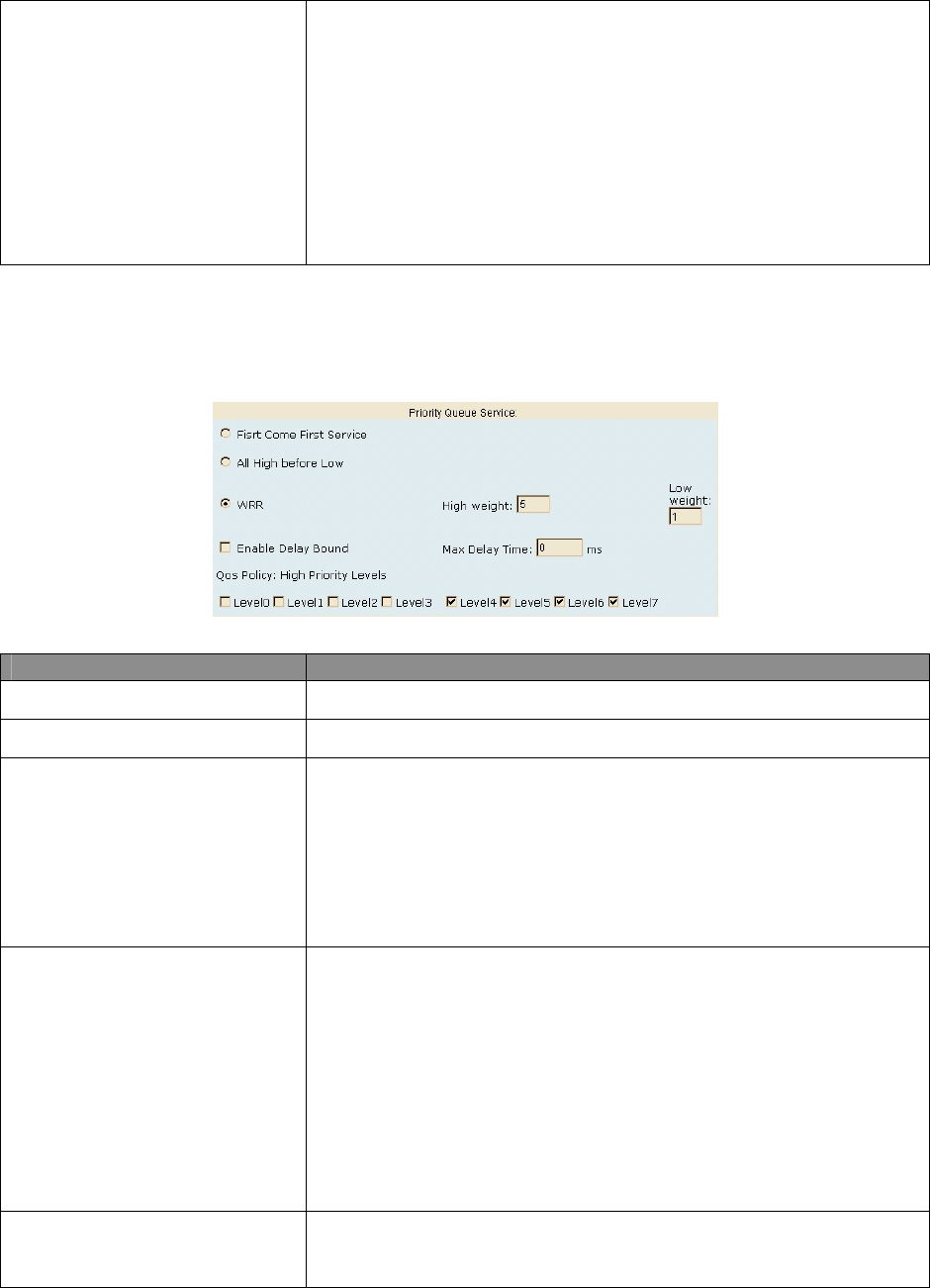
Priority Queue Service Settings
Parameter Description
First Come First Service
The sequence of packets sent is depend on arrive order.
All High before Low
The high priority packets sent before low priority packets.
Weighted Round Robin
Select the preference given to packets in the switch’s high-priority
queue. These options represent the number of high priority packets
sent before one low priority packet is sent. For example, 5 High: 2
Low means that the switch sends 5 high priority packets before
sending 2 low priority packets.
Enable Delay Bound
Limit the low priority packets queuing time in the switch. If the low
priority packets exceed Max Delay Time, it will be sent. ‘Max bridge
transit delay bound control’ must be enabled before this function will
operate.
Range: 1~255 ms.
Default Max Delay Time: 255ms.
QoS Policy: High Priority
Levels
0~7 priority level can map to high or low queue.
17