User’s Manual IP Telephony Gateway Model No.: SP5001/S http://www.micronet.info Version 2.
Table of Contents 1. 2. 3. 4. 5. SP5001/S OVERVIEW........................................................................................................ 7 1.1 FEATURES OF SP5001/S ............................................................................................... 7 1.2 DEFAULT SETTINGS......................................................................................................... 8 1.3 FRONT PANELS ............................................................................
9. VOICE SETTING SCREEN..............................................................................................37 10. PHONE PATTERN SCREEN.......................................................................................39 11. SUPPORT FUNCTION SCREEN ...............................................................................40 12. PHONE BOOK SCREEN.............................................................................................41 13. DSCP CONFIGURATION SCREEN.............
List of Figures Figure 1. Login Screen..............................................................................................................15 Figure 2. SP5001/S web configuration welcome screen.....................................................16 Figure 3. Network Interface Screen ........................................................................................17 Figure 4. Network Interface ...................................................................................................
Figure 36. Change password Screen .....................................................................................52 Figure 37. quit command list ....................................................................................................64 Figure 38. debug command list ...............................................................................................64 Figure 39. debug –print command list ....................................................................................
List of Tables Table 1. SP5001/S LEDs Descriptions ...................................................................................10 Table 2. Navigation Pane l Links...............................................................................................16 Table 3. H323 Configuration.....................................................................................................33 Table 4. SIP Information..........................................................................................
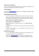
About this User’s Manual This user’s manual gives hardware specifications and explains web configuration and command line configuration for SP5001/S FXS Gateway. Online Upgrade Please refer to www.micronet.info for online Technical Support and additional support documentation. General Syntax Conventions Ÿ Mouse action sequences are denoted using a comma.
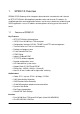
1. SP5001/S Overview SP5001/S FXS Gateway which integrates data and voice in one device and is based on IETF RFC 2543 bis-09 compliance provides voice and fax over IP networks. Its simplified operation and configuration features are the most suitable for residential and SOHO application. Just an IP address and one phone set bring you to Voice over IP world. 1.
Ÿ Ÿ Ÿ Ÿ One RJ11 Telephone Port (FXS). DC 12V input. System Monitoring System status (Link, Ready, Status, TEL, Power). Remote Firmware Upgrade You can use FTP/TFTP to perform configuration backup/restore and firmware upgrade for SP5001/S from a remote location. Security Password protection for system management 1.2 Default Settings The following are the settings of the default profile Ÿ Login: root Ÿ Password: Null (default) 1.2.1 IP Parameters Ÿ IP Address = 10.1.1.3 Ÿ Subnet mask = 255.0.0.
1.3 Front Panels The LEDs on the front panel indicate the operational status of the Gateway. (1) Console 1.
1.5 Hardware Specifications These are the hardware details of SP5001/S. 1.5.1 SP5001/S LEDs Table 1. SP5001/S LEDs Descriptions LEDs Functions Status PWR Power Green TEL TEL Red READY Ready Green Active Description On The Power is on Off The Power is off On The Telephone is Off-Hook. Off The Telephone is On-Hook. Slow Blinking Normal mode. Fast Blinking Downloading mode.
1.5.2 Back Panel Port Ethernet Port: Ethernet port is for connecting SP5001 to network, transmit rate supports 10/100 Base-T. Ethernet connector(LAN) COM Port: RS232 console port (DB-9pin male connector) Note: use straightforward cable to connect to your computer. PINOUTS Pin Name Dir Description 2 RXD Receive Data 3 TXD Transmit Data 5 GND System Ground TEL Port: RJ-11 connector, FXS interface. To connect analog phone sets or trunk line of PABX.
12V DC Port: DC Power supply. 1.5.3 Back Panel Connections This section outlines how to connect your SP5001/S to the LAN and the WAN. In the case of connecting a Cable Modem you must connect the coaxial cable from your cable service to the threaded coaxial cable connect on the back of the cable modem. Step 1. Connecting the Console Port For the initial configuration of your SP5001/S, you need to use terminal emulator software on a workstation and connect it to the console port of SP5001/S.
Step 5. Grounding SP5001/S If you want to ground SP5001/S then connect a grounded wire to the F.G. (Frame Ground) of SP5001/S. 1.6 Additional Installation Requirements In addition to the contents of your package, there are other hardware and software requirements you need before you can install and use your SP5001/S. These requirements include: 1. 2. 3. A computer with an Ethernet NIC (Network Interface Card) installed.
Step 3. Click whether the TCP/IP Protocol has already been installed onto your computer’s Ethernet card. Note that TCP/IP Protocol can be installed for a computer’s Dial-Up Adapter as well as for the Ethernet card. - If yes, go to set 7. - If no, click the “Add” button Step 4. Double-click “Protocol” in the Select Network Component Type or highlight “Protocol” then click “Add”. Step 5. Highlight “Microsoft” under the list of manufacturers. Step 6.
2. Web Configuration with FXS Introduction 2.1 Accessing the Web Configuration The embedded web configuration allows you to use a web browser to manage SP5001/S. You will need a computer with and Ethernet 10BaseT, 100Base-TX Network Interface Card (NIC). Connect to the LAN port in the FXS. Use Internet Explorer 5.5 and later or Netscape Navigator 6 and later versions. Use the following instructions to login on to the web configuration. Step 1. Step 2. Start your web browser.
Figure 2. SP5001/S web configuration welcome screen The following table describes the screen. Table 2. Navigation Panel Links LABEL DESCRIPTION Network Interface This link takes you to a screen where you can configure SP5001/S Network Interface Information. SIP Information This link takes you to a screen where you can setup up SIP Information. System Configuration This link takes you to a screen where you can set up System Configuration.
LABEL DESCRIPTION Flash Clean This link takes you to a screen where you can click flash memory information and configuration. Commit Data This link takes you to a screen where you can click save your changes to the non-volatile memory. Reboot System 2.3 This link takes you to a screen where you can click to reboot SP5001/S. Saving Your Configuration Click OK to save your changes back to volatile memory.
3. Initial Configuration This chapter describes the procedure for the initial configuration of SP5001/S. Refer to the relevant chapters in this User’s Manual for descriptions of the fields and buttons within individual screens. 3.1 General Configuration SP5001/S has a factory default IP address of 10.1.1.3 and a subnet mask of 255.0.0.0. 3.2 Static IP address Step 1. To configure the IP address of SP5001/S, click Network Interface on the navigation panel.
Figure 5. Commit Data Step 3. Click Reboot Data on the navigation panel. In the Reboot FXS System screen, click the Reboot button. It will take 40 seconds to reboot. Figure 6. Reboot FXS System Step 4. Close the current browser windows and launch your web browser again. Enter the new IP address in the Location or Address field. Press [Enter].
3.3 DHCP mode Step 1. To configuration the IP address of SP5001/S for DHCP Mode, click Network Interface on the navigation panel. In the Network Interface screen, enable the DHCP function if you are using the cable modem or DHCP server and click the OK button. Figure 7. Network Interface Step 2. Click Commit Data on the navigation panel. In the Commit Data screen, click the Commit button. Step 3. Click Reboot Data on the navigation panel. In the Reboot FXS System screen, click the Reboot button.
3.4 IP Sharing Configuration One Sets SP5001/S The function is for user whose network environment is behind IP Sharing device. It is said SP5001/S is connected to the IP Sharing device (Router). An example such ADSL network is like the following. The WAN IP Address obtained from ADSL has two kinds of methods. One is fixed IP Address, while user applies for one or more fixed IP Addresses. Another is dynamic IP Address while user applies for dial-up connection way.
Please see following for example: >Advanced setting > NAT setting > DMZ Host setting DMZ Host setting Activate DMZ DMZ Host IP : 192 . 168 . 1 . 5 Step 1. To configuration the IP address of SP5001/S for IP Sharing Mode, click Step 2. Network Interface on the navigation panel. In the Network Interface screen, enter the IP address, Subnet mask and the default gateway in the network table.
Step 3. Click Commit Data on the navigation panel. In the Commit Data screen, Step 4. click the Commit button. In the Commit Data screen to Display Commit to Flash OK! when the Commit Data Ok. Click Reboot Data on the navigation panel. In the Reboot FXS System Step 5. screen, click the Reboot button. It will take 40 seconds to reboot. Close the current browser windows and launch your web browser again. Enter the new IP address in the Location or Address field. Press [Enter].
See following for example. >Advanced setting > NAT setting > Port Redirection Active Configuration Items Service name Protocol Actual Port Virtual IP Virtual Port Enable 1 1 UDP 5060 192.168.1.10 5060 v 2 2 UDP 16384 192.168.1.10 16384 v 3 3 UDP 16394 192.168.1.10 16394 v 4 4 UDP 5061 192.168.1.11 5061 v 5 5 UDP 26384 192.168.1.11 26384 v 6 6 UDP 26394 192.168.1.
the DMZ Host.
4. Making a VoIP Call This Chapter covers the basic configuration the gateway for making VoIP calls. One is the Peer-to-Peer mode, another is Proxy routed mode. The configurations and functions are different. Please make sure about the mode you want and follow up the step to configure your gateway. 4.1 Step 1. Configure the gateway into the Peer-to-Peer mode To Configuration the SIP Configuration of SP5001/S, click SIP Information on the navigation panel.
Figure 10. Phone Book Step 3. E.g. enter the Index: 1, Name: test1, IP address: 192.168.4.72 and e164: 200 of the destination and click the Add Data button. Figure 11.
Step 4. On table will display on the first index. Figure 12. Phone Book Step 5. Click Commit Data on the navigation panel. In the Commit Data screen, Step 6. click the Commit button. Click Reboot Data on the navigation panel. In the Reboot FXS System screen, click the Reboot button. It will take 40 seconds to reboot.
4.2 Configure the gateway into the Proxy routed mode Step 1. To configuration the SIP Configuration of SP5001/S, click SIP Information Step 2. on the navigation panel. In the SIP Information screen, select Proxy routed Mode function. To change the SIP information from your service provider Proxy IP Address, Line1 Number, Lin1 Account, Line1 Password, (e.g. Proxy IP Address: 192.168.4.192, (e.g. Line1 Number: 60921, Line1 Account: 60921, Line1 Password: 609), and click the OK button. Figure 13.
5. Upgrade ROM Version This Chapter covers the basics of how to upgrade ROM Version. 5.1 Before you start downloading 1. Please confirm Host PC, which is installed as TFTP / FTP server, and device are in available network. 2. Remember the current configuration, such as [pbook], [SIP]. 5.2 Step 1. Update Application Version Update the ROM Version of SP5001/S. Click ROM Configuration on the navigation panel.
Figure 15. ROM File Upgrade OK Step 3. Click Flash Clean on the navigation panel. In the Flash Clean screen, click the CLEAN button. In the Flash Clean screen to Display Flash cleaned!! Please reboot your system!! when the Flash Clean Ok. Figure 16.
Step 4. Click Reboot Data on the navigation panel. In the Reboot FXS System Step 5. screen, click the Reboot button. It will take 40 seconds to reboot. Close the current browser windows and launch your web browser again. Enter the IP address in the Location or Address field. Press [Enter].
6. Network Interface Screen Click Network Interface in the navigation panel and open the Network Interface Screen. Use this screen to setup Network Interface identification information for SP5001/S. Figure 17. Network Interface The following table describes this screen. Table 3. H323 Configuration LABEL DESCRIPTION IP Address Enter the IP Address of SP5001/S in dotted decimal notation for e.g. 192.168.4.92. Range of IP Address setting (0.0.0.0~255.255.55.255).
LABEL DESCRIPTION SNTP Server Address Set specify a SNTP Server as network time source in dotted decimal notation for e.g. 168.95.192.12. GMT Set local time zone according to GMT e.g. 8. IP Sharing Select enable IP Sharing function, when you specify usage of and IP Sharing device. UPnP Select enable/disable UPnP function. IP Sharing Server Enter specify a global fixed IP Address, user can add this IP Address in Address dotted decimal notation for e.g. 210.11.22.33.
7. SIP Information Screen Click SIP Configuration in the navigation panel and open the SIP Information Screen. Figure 18. SIP Information The following table describes this screen. Table 4. SIP Information LABEL DESCRIPTION RUN Mode Select Proxy mode or Peer-to-Peer mode Proxy IP Address Set Proxy IP Address in dotted decimal notation e.g.192.168.4.71. Proxy Port SIP local UDP port number (5060~5070), default: 5060. Domain Set Domain Name of Proxy Server.
8. System Configuration Screen Click System conf in the navigation panel and open the System Configuration Screen. Figure 19. System Configuration The following table describes this screen. Table 5.
9. Voice Setting Screen This Chapter covers voice is associated with the audio setting information. Click Voice Setting in the navigation panel and open the Voice Setting Screen. Figure 20. Voice Configuration The following table describes this screen. Table 6. Voice Configuration LABEL DESCRIPTION Codec Priority Set priority preference of installed codes, G.723, G.711A, G.711U, G.729. Frame Size Set Specify sending packet size, G.723, G.711A, G.711U, G.729.
LABEL DESCRIPTION Optimized Factor Setting Optimized Factor (Jitter). (Jitter): OK Note: Click OK to save your changes back to volatile memory. Well understand the application before you change voice parameters, because this might cause incompatibility.
10. Phone Pattern Screen The progress tone of SP5001/S is configurable. Default tone value is set according to U.S. tone specification. Users may adjust the values according to their own country’s tone specification or users-defined tone specification. Click Phone Pattern in the navigation panel and open the Phone Pattern Screen. Figure 21. Phone Pattern The following table describes this screen. Table 7.
11. Support Function Screen Click Support Function in the navigation panel and open the Support Function Screen. Figure 22. Support Function The following table describes this screen. Table 8 Support Configuration LABEL DESCRIPTION T.38 FAX Select enable/disable for T.38 FAX Function. OK Click OK to save your changes back to volatile memory.
12. Phone Book Screen This Chapter covers Phone Book function allows users to define their own numbers, which mapping to real IP address. It is effective only in peer-to-peer mode. When adding a record to Phone Book, users do not have to reboot the machine, and the record will be effective immediately. Click Phone Book in the navigation panel and open the phone Book Screen. Figure 23. Phone Book The following table describes this screen. Table 9.
LABEL DESCRIPTION Name Set up a descriptive name. IP Address Set up IP Address or Domain Name. e164 No. Set up e164 (telephone) number Add Data Add a record to Phone Book. Delete Data Delete a record to Phone Book. Note: The e164 number defined in phone book will fully carry to destination. It is not just a representative number for destination’s IP Address.
13. DSCP Configuration Screen This Chapter covers IP Packet ToS (type of Service)/Differentiated Service configuration. Click DSCP Configuration in the navigation panel and open the DSCP Configuration Screen. Figure 24. DSCP Configuration The following table describes this screen. Table 10. DSCP Configuration LABEL DESCRIPTION Assured Forwarding Select Delay priority and Drop Precedence. (AF) PHB Expedited Forwarding Select TOS value as EF. (EF) PHB Default Select TOS value as 0.
14. Password Screen Click Password in the navigation panel to open the Password Configuration screen. Use the Password Configuration to set root and administrator password for SP5001/S. It is highly recommended that you change the default password (“Null”). Figure 25. Password Configuration The following table describes this screen. Table 11. Password LABEL DESCRIPTION Username Select root or administrator different options from the drop-down list box.
15. ROM Upgrade Screen Click ROM Upgrade in the navigation panel and open the ROM Configuration Screen. Figure 26. ROM Configuration The following table describes this screen. Table 12. ROM Configuration LABEL DESCRIPTION FTP/TPFT Server IP Enter the FTP or TFTP Server IP Address. Address Target File Name Enter the file name prepared to upgrade. Method Select download method as FTP or TFTP.
16. Flash Clean Screen Click Flash Clean in the navigation panel and open the Flash Clean Screen. Figure 27. Flash Clean The following table describes this screen. Table 13. Flash Clean LABEL DESCRIPTION Clean Clean all of the user-defined values to factory default. Note: It is only executed by user whose login name is root. All configurations in command [ifaddr] will be kept.
17. Commit Data Screen Click Commit Data in the navigation panel and open the Commit Data Screen. Figure 28. Commit Data The following table describes this screen. Table 14. Commit Data LABEL DESCRIPTION Commit Save changes after configuring SP5001/S.
18. Reboot System Screen Click Reboot System in the navigation panel and open the Reboot FXS System screen. Figure 29. Reboot FXS System The following table describes this screen. Table 15. Reboot FXS System LABEL DESCRIPTION Reboot After commit command, type reboot to reload SP5001/S in new configuration.
19. Command List This chapter introduces the command line interface and lists all of the commands. 19.1 Hyper Terminal Setting A terminal emulator is needed when using RS-232 port to configure SP5001/S. Here, we use Microsoft HyperTerminal to depict how to set up terminal emulator: Step 1. Execute the Hyper Terminal program, and then the following windows will pop-up on the screen. (STARTàProgram filesà Accessoriesà CommunicationàHyper Terminal) Figure 30. Hyper Terminal Setting Step 2.
Step 3. After pressing OK button, the next window will appear, and then choose COM1/2 Port, which you are going to use. Figure 32. “Connect To” Page Step 4. Configure the COM Port Properties as following: Bits per second: 9600, Flow control: None, Press OK button, and then start to configure SP5001/S. Figure 33.
19.2 Power Up Your SP5001/S At this point, you should have connected the console port, the LAN Port, the WAN port and the power port to the appropriate devices or lines. Plug the power adapter into a wall outlet. The Power LED should be on. The Status LED will come on after the system tests are complete. The WAN LED and one of the LAN LEDs come on immediately after the Status LED come on, if connections have been made to the LAN and WAN ports.
Set Password To set your own password in root login name, just input command “passwd –set root ****”. For example, if password of root account is prepared as ”voip”, configuration is usr/config$ passwd -set root voip Setting Login: root Password: voip OK usr/config$ Figure 36. Change password Screen 19.3 Command Structure in SP5001/S You can use text command lines for software configuration. The rules of the commands are listed next. The command keywords are in courier new font. 1. 2.
19.3.3 Application Mode Configuration It is including Basic mode, such as Proxy Server and Peer-to-Peer, and Advanced mode, IP -Sharing mode. It will be detailed in the next Chapter. 19.3.4 Saving Your Configuration Save the change of configurations for SP5001/S and apply the new configurations by rebooting the device. Step 1. Confirm the changed configurations; input “commit” and press “enter” to save it. Step 2. Input “reboot” then press, “enter” to restart SP5001/S. Step 3.
command. For detail, please refer to Chapter 19.7.13 [security] command. An example is demonstrated below: usr/config$ security – line 1 – name 12345 – password 12345 Note: This is to set username (userid) as “12345”, password as “12345” into line1, which means line1 can accept incoming calls after successfully registered to Proxy server. Step 2. You must specify Proxy address obtained from your service provider. And the Proxy address can be IPv4 address as well as DNS name.
Expires:3600 Registering to: Sip:80.248.33.37 with the following : To:sip:sipcenter1165@80.248.33.37 From:sip:sipcenter1165@80.248.33.37 Contact:sip:sipcenter1165@210.59.163.143 Expires:3600 Account: sipcenter1123 registration succeeded Account: sipcenter1165 registration succeeded AC4804[0] is ok successful Initialize OSS libraries...OK! VP v1.40 stack open successfully. login: 19.4.2 Peer-to-Peer Mode Peer-to-Peer Mode allows users to call other VoIP devices without the proxy server.
Note: The command is to add a record onto PhoneBook. After the command completed, you can type “pbook –print” to see if the input record is correct. When adding a record to Phone Book, users do not have to reboot the machine, and the record will be effective immediately. For phonebook configuration, please refer to Chapter 19.7.9. 19.4.3 Behind IP-Sharing Mode One Set of SP5001/S The function is for user whose network environment is behind IP Sharing device.
Fixed IP Address: usr/config$ ifaddr – ipsharing 1 210.11.22.33 Note: With Dynamic WAN IP Address, when the WAN IP is changed, we need to change the external IP of SP5001/S using above command. 5. IP Sharing device must have a function to do IP/Port mapping. Some is named as DMZ; some is named as virtual server. The VoIP messages from WAN have to completely pass forward to the LAN. It is said if SP5001/S is assigned a virtual fixed IP Address such as 192.168.1.
Two Sets of SP5001/S 1. The WAN IP Address obtained from ADSL has two kinds of methods. One is fixed IP Address, while user applies for one or more fixed IP Addresses. Another is dynamic IP Address while user applies for dial-up connection way. 2. The LAN IP Address of User’s PC can be set as DHCP client in order to gain a valid one. 3. Assign an IP address to each set using DHCP or fixed address. 4. Enable the IP Sharing function for each set using following command.
>Advanced setting > NAT setting > Port Redirection Active Configuration Items Service name Protocol Actual Port Virtual IP Virtual Port Enable 1 1 UDP 5060 192.168.1.10 5060 v 2 2 UDP 16384 192.168.1.10 16384 v 3 3 UDP 16394 192.168.1.10 16394 v 4 4 UDP 5061 192.168.1.11 5061 v 5 5 UDP 26384 192.168.1.11 26384 v 6 6 UDP 26394 192.168.1.11 26394 v 7 --- 0 0 x 8 --- 0 0 x 9 --- 0 0 x 10 --- 0 0 x Note: 1.
19.4.4 PPPoE Mode Press [?] or [help] to list all commands, including PPPoE one. Step 1. pppoe –dev 1 : switch the IP configurations to PPPoE Step 2. pppoe –open : open the connection Step 3. pppoe –id : input the user ID provided by your ISP Step 4. pppoe –pwd : input the password provided by your ISP Step 5. pppoe –reboot : Reboot the device once after disconnection After the configurations are done, [commit] and [reboot] the device.
Enable the PPPoE function of SP5001/S Command: usr/config$ pppoe -dev 1 Save the configuration and initiate the PPPoE connection. Command: usr/config$ commit usr/config$ reboot 19.5 How to upgrade Before you start downloading 1. Please confirm Host PC, which is installed as TFTP / FTP server and device is in available network. 2. Remember the current configuration, such as [pbook], [SIP]. Upgrade steps: Step 1. [rom –print] It will list current version and default download method.
B. 2MB Rom: usr/config$ rom –boot2m –s 192.168.1.1 –f 2m4asipfxs.104b Description: -app / -boot2m means the prepared upgrade Rom; -s means where the TFTP / FTP server IP Address is; -f is the Rom file name. Step 4. Download complete A. B. Application Rom: Use command [flash -clean] to clear old configurations. It will keep all configurations in [ifaddr] and [pppoe]. 2MB Rom: All configurations will be back to default value, including IP Address.
19.6 Commands in SP5001/S The following table lists all of the commands that you can use in SP5001/S. Refer to the following chapters for descriptions of commonly used commands. This user’s guide describes commands that are helpful for configuring SP5001/S. Using commands not documented in the user’s guide can damage the unit and possibly render it unusable. Table 16. Commands in SP5001/S Command DESCRIPTION help help/man/?[command] quit quit/exit/close. debug show debug message.
19.7 System Commands Overview 19.7.1 [quit] Type quit will quit configuration mode. And turn back to login prompt. usr/config$ quit Disconnecting... login: root Welcome to Terminal Configuration Mode Please enter your configuration item Figure 37. quit command list Note: It is recommanded that type the “quit” command before you leave the console. If so, SP5001/S will ask password again when next user connects to console port. 19.7.
Parameter Usages: -status -add -sip -msg -delete -open -close Display the enabled debug flags. Add debug flag. sip related information voice related information Remove specified debug flag. Start to show debug messages. Stop showing debug messages. usr/config$ debug -status Current debug type enabled : Debug Mode is close DEBUG-> usr/config$ Figure 39. debug –print command list 19.7.3 [reboot] After commit command, type reboot to reload SP5001/S in new configuration.
19.7.4 [flash] Save changes after configuring SP5001/S. usr/config$ flash Flash memory information and configuration Usage: flash -clean Note: This command will clean the configuration stored in the flash and reboot it. usr/config$ Figure 41. flash command list Parameter Usages: -clean clean all the user defined value, and reboot SP5001/S in factory default mode. Note: It is recommended that use “flash –clean” after application firmware id upgraded.
19.7.5 [commit] Save changes after configuring SP5001/S. usr/config$ commit This may take a few seconds, please wait.... Commit to flash memory ok! usr/config$ Figure 43. commit command list Note: Users shall use commit to save modified value, or they will not be activated after system reboot. 19.7.6 [ifaddr] Configure and display network information.
Parameter Usages: -print -ip -mask -gate -dhcp -sntp -dns address. print current IP setting and status assigned IP address for SP5001/S internet subnet mask IP default gateway Dynamic Host Configuration (1 = ON; 0 = OFF) Simple Network Time Protocol (1 = ON; 0 = OFF) When SNTP function is activated, users have to specify a SNTP server as network time source. An example is demonstrated below: Specify Primary (-dns 1) or Secondary (-dns 2) DNS Server IP usr/config$ ifaddr -dns 1 168.95.1.
19.7.7 [time] When SNTP function of SP5001/S is enabled and SNTP server can be found as well, type time command to show current network time. usr/config$ time Current time is WED SEP 17 12:36:49 2003 usr/config$ Figure 46. time command list 19.7.8 [ping] Use ping to test whether a specific IP is reachable or not. For example: if 192.168.1.2 is not existing while 210.63.15.32 exists. Users will have the following results: usr/config$ ping 192.168.1.2 no answer from 192.168.1.2 usr/config$ ping192.168.
19.7.9 [pbook] Phone Book function allows users to define their own numbers, which mapping to real IP address. It is effective only in peer-to-peer mode. When adding a record to Phone Book, users do not have to reboot the machine, and the record will be effective immediately.
SP5001/S will give each record a automatic sequence number as index. -add add a new record to phone book. When adding a record, users have to specify name, IP, and e164 number to complete the command. -search search a record in phone book. The searching criteria can be name, IP, or e164. -delete delete a specific record. “pbook –delete 3” means delete index 3 record. -insert add a new record and force to assign a specific index number for it. -modify modify an existing record.
19.7.10 [pppoe] Display PPPoE related information. usr/config$ pppoe PPPoE device information and configuration Usage: pppoe [-print]|[-open]|[-close] pppoe [-dev on/off][-id username][-pwd password] -print -dev -open -close -id -pwd -reboot Display PPPoE device information. Enable(=1) or Disable(=0) device. Open PPPoE connection. Disconnect PPPoE connection. Connection user name. Connection password. Reboot after remote host disconnection. usr/config$ Figure 50.
19.7.11 [sysconf] This command displays system information and configurations. usr/config$ sysconf System information and configuration Usage: sysconf [-idtime digit] [-bf digit] [-keypad dtmf] [-faxtype type][-2833type type][-lcdrop ON/OFF] [-droptime digit][-eod digit] sysconf -print -print -idtime -bf -keypad Display system overall information and configuration. Inter-Digits time.(1~10 sec) BusyForward.(ON:1 / OFF:0) Select DTMF type: 0=In-band, 1=RFC2833.
usr/config$ sysconf -print System information Inter-Digits time : 3 BusyForward : OFF Keypad DTMF type : In-band End of Dial Digit : # RFC2833 Payload Type : 96 FAX Payload Type : 101 Disconnect Supervision : OFF Loop Current Drop Time(ms) : 500 usr/config$ Figure 53.
19.7.12 [sip] This command is to configure SIP related parameters. usr/config$ sip SIP stack information and configuration Usage: sip [-mode pxmode] sip [-px address] [-domain domain] [-prefix prefixstring] [-line1 number] [-expire t1] [-port udpPort] [-rtp rtpPort] sip -print -print -mode -px name) -pxport -domain used, Display SIP stack information and configuration. Configure as Proxy mode or Peer-to-Peer mode. Proxy server address. (Proxy IPv4 address or Proxy dns Proxy server port.
-port -rtp of the registration information. SIP local UDP port which uses to listen incoming SIP Messages. Specify the RTP received port number. Note: One will need to configure port and rtp parameters only when you deploy two or more sets behind the IP sharing device. usr/config$ sip -print Run Mode Proxy address Proxy port Domain Prefix string Line1 SIP listen port RTP receive port Expire usr/config$ : PROXY MODE : 10.1.1.2 : 5060 : null : null : 1001 : 5060 : 16384 : 3600 Figure 55.
19.7.13 [security] This command is used to configure the account information included username and password obtained from the service provider usr/config$ security Security information and configuration Usage: security [-name username] [-pwd password] security -print -print Display system account information and configuration. -line Specify which line number you want to set the account. -name Specify user name. -pwd Specify password. Example: security -line 1 -name 1001 -pwd 1001 usr/config$ Figure 56.
19.7.14 [voice] The voice command is associated with the audio setting information. There are four voice codecs supported by SP5001/S.
-priority parameter, 20/40/60ms is applicable to G.711u/a law, and G.729 codec, while 30/60ms is applicable to G.723.1 codec. codec priority while negotiating with other SIP device. This parameter determines the listed sequence in the media header of SDP body of SIP INVITE message. The codec listed in left side has the highest priority when both parties determining final codec. User can also select the particular codec without others.
usr/config$ voice -print Voice codec setting relate information Sending packet size : G.729A : 40 ms G.723.1 : 60 ms G.711U : 40 ms G.711A : 40 ms Priority order codec : g729a g7231 g711u g711a Volume levels : voice volume : 25 input gain : 25 dtmf volume : 23 No sound compress & CNG : G.729A : There is no setting G.723.1 : Off G.711(U-Law) : Off G.711(A-Law) : Off Echo canceller : On Jitter buffer : Min Delay : 90 Max Delay : 150 usr/config$ Figure 59. voice –print command list 19.7.
Note: it is not recommended to change the value in this command, only if users do know well the application. This might cause incompatibility with other devices. usr/config$ support -print Special Voice function support manipulation T.38(FAX) support : Disabled usr/config$ Figure 61. support –print command list 19.7.16 [tos] IP Packet ToS (type of Service)/Differentiated Service configuration.
19.7.17 [phone] The progress tone of SP5001/S is configurable. Default tone value is set according to U.S. tone specification. Users may adjust the values according to their own country’s tone specification or users-defined tone specification.
Parameter Usages: -print print current call progress tone configurations (ring: ring tone, rbt: ring back tone, bt: busy tone, dt: dial tone). This parameter should be accompanied with tone type.
19.7.18 [rom] ROM file information and firmware upgrade function. usr/config$ rom ROM files updating commands Usage: rom [-print] [-app] [-boot] [-dsptest] [-dspcore] [-dspapp] -s TFTP/FTP server ip -f filename rom -print -print show versions of rom files.
usr/config$ rom -print Download Method : Hardware Ver. : Boot Rom : Application Rom : DSP App : DSP Kernel : DSP Test Code : usr/config$ TFTP 3.0b sdboot.200 4asipfxs.106 48302ce3.140 48302ck.140 483cbit.bin Figure 67. rom –print command list 19.7.19 [passwd] For security concern, users have to input the password before entering configuration mode. “passwd” command is for password setting purpose.