
Network Router User Manual

12
12V DC Port:
DC Power supply.
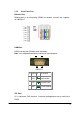
1.5.3 Back Panel Connections
This section outlines how to connect your SP5001/S to the LAN and the WAN.
In the case of connecting a Cable Modem you must connect the coaxial cable
from your cable service to the threaded coaxial cable connect on the back of
the cable modem.
Step 1. Connecting the Console Port
For the initial configuration of your SP5001/S, you need to use terminal
emulator software on a workstation and connect it to the console port of
SP5001/S. Connect the 9-pin end of the console cable to the console port of
SP5001/S and the other end to a serial port (COM1, COM2 or other COM port)
of your workstation. You can use an extension RS-232 cable if the enclosed
one is too short. After the initial setup, you can modify the configuration
remotely through telnet connections.
Step 2. Connecting SP5001/S to WAN
Connect the WAN port (silver) on SP5001/S to the Ethernet port on the cable
modem using the cable that came with your cable modem. The Ethernet port
on the cable modem is sometimes labeled “PC” or “Workstation”.
Step 3. Connecting PC to LAN
If you have more than one PC, you must use an external hub. Connect the
10/100M LAN Port (gold) on SP5001/S to a port on the hub using a straight
through Ethernet cable. If you only have one PC, you can connect SP5001/S
to the PC directly without a hub. For a single PC, connect the 10/100M LAN
port on SP5001/S to the Network Adapter on the PC using a crossover cable
(red tag).
Step 4. Connecting the Power Adapter to your SP5001/S
Connect the power adapter to the port labeled POWER on the rear panel of
SP5001/S.
Caution:
To prevent damage to SP5001/S, first make sure you have the correct
AC power adapter. Please see the Appendices for AC power adapter
specifications for your region.