User’s Manual EtherFast 10/100M Smart Switch Model No.: SP648B http://www.micronet.
FCC Warning This equipment has been tested and found to comply with the regulations for a Class A digital device, pursuant to Part 15 of the FCC Rules. These limits are designed to provide reasonable protection against harmful interference when the equipment is operated in a commercial environment. This equipment generates, uses, and can radiate radio frequency energy and, if not installed and used in accordance with this user’s guide, may cause harmful interference to radio communications.
UL Warning a) Elevated Operating Ambient Temperature- If installed in a closed or multi-unit rack assembly, the operating ambient temperature of the rack environment may be greater than room ambient. Therefore, consideration should be given to installing the equipment in an environment compatible with the manufacturer's maximum rated ambient temperature (Tmra).
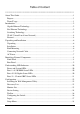
Table of Content -----------------------------------------------------------About This Guide.................................................................................................................1 Purpose ............................................................................................................................1 Terms/Usage ....................................................................................................................1 Introduction............................
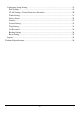
Configuring Setup Setting..............................................................................................19 Port Settings...............................................................................................................19 VLAN Settings (Virtual Local Area Network) ..........................................................20 Trunk Setting .............................................................................................................21 Device Status ...................
ABOUT THIS GUIDE Congratulations on your purchase of the 48+4G-Port 10/100/1000Mbps Gigabit Ethernet Web Smart Switch. This device integrates 1000Mbps Gigabit Ethernet, 100Mbps Fast Ethernet and 10Mbps Ethernet network capabilities in a highly flexible package. Purpose This guide discusses how to install your 48+4G-Port 10/100/1000Mbps Gigabit Ethernet Web Smart Switch.
INTRODUCTION This chapter describes the features of the 48+4G-Port 10/100/1000Mbps Gigabit Ethernet Web Smart Switch and some background information about Ethernet/Fast Ethernet/Gigabit Ethernet switching technology. Gigabit Ethernet Technology Gigabit Ethernet is an extension of IEEE 802.
100Mbps Fast Ethernet is a standard specified by the IEEE 802.3 LAN committee. It is an extension of the 10Mbps Ethernet standard with the ability to transmit and receive data at 100Mbps, while maintaining the CSMA/CD Ethernet protocol. Since the 100Mbps Fast Ethernet is compatible with all other 10Mbps Ethernet environments, it provides a straightforward upgrade and takes advantage of the existing investment in hardware, software, and personnel training.
VLAN (Virtual Local Area Network) A VLAN is a group of end-stations that are not constrained by their physical location and can communicate as if a common broadcast domain, a LAN. The primary utility of using VLAN is to reduce latency and need for routers, using faster switching instead. Other VLAN utility includes: Security, Security is increased with the reduction of opportunity in eavesdropping on a broadcast network because data will be switched to only those confidential users within the VLAN.
Easy setting via Web Management Utility Standard 19” Rack-mount size 5
UNPACKING AND INSTALLATION This chapter provides unpacking and installation information for the Switch. Unpacking Open the shipping cartons of the Switch and carefully unpacks its contents.
Figure 1. Combine the Switch with the provided screws Then, use screws provided with the equipment rack to mount each switch in the rack. Figure 2. Mount the Switch in the rack Connecting Network Cable The Switch supports 10Mbps Ethernet or 100Mbps Fast Ethernet and it runs both in half and full duplex mode using two pair of Category 5 cable.
IDENTIFYING EXTERNAL COMPONENTS This chapter describes the front panel, rear panel, and LED indicators of the Switch. Front Panel The figure below shows the front panels of the Switch. Figure 3. Front panel of 48+4G-port Gigabit Ethernet Switch LED Indicator: Comprehensive LED indicators display the status of the switch and the network (see the LED Indicators chapter below).
Rear Panel Figure 4. Rear panel of the Switch AC Power Connector: This is a three-pronged connector that supports the power cord. Plug in the female connector of the provided power cord into this connector, and the male into a power outlet. Supported input voltages range from 100-240V AC at 50-60Hz.
UNDERSTANDING LED INDICATORS The front panel LEDs provides instant status feedback, and, helps monitor and troubleshoot when needed. Figure 5. LED indicators of the Switch Power and System LEDs POWER: Power Indicator On : When the Power LED lights on, the Switch is receiving power. Off : When the Power turns off or the power cord has improper connection. SYSTEM: Management Indicator Blinking : When the CPU is working, the System LED is blinking. On/Off : The CPU is not working.
Off : No link. SPEED: On (Green) On (Amber) Off : When the green light is on, the respective port is connected to a 1000Mbps Gigabit Ethernet network. When the Amber light is on, the respective port is connected to a 100Mbps Fast Ethernet network. : When the respective port is connected to a 10Mbps Ethernet or No link Ports 51~ 52 mini-GBIC Status LEDs Link/ACT: Link/Activity On : When the mini-GBIC module is installed and connected to a network, the Link/ACT LED lights on.
CONFIGURATION Through the Web Browser you can configure the Switch such as VLAN, Trunking, QoS… etc. With the attached Web Management Utility, you can easily discover all the Web Management Switch, assign the IP Address, changing the password and upgrading the new firmware. Installing the Web Management Utility The following gives instructions guiding you through the installations of the Web Management utility. 1. Insert the Utility CD in the CD-Rom Drive. 2.
Discovery List This is the list where you can discover all the Web management devices in the entire network. By pressing the “Discovery” button, you can list all the Web Management devices in the discovery list. Double click or press the “Add to monitor list” button to select a device from the Discovery List to the Monitor List. System word definitions in the Discovery List: z z z z z z z z z MAC Address: Shows the device MAC Address. IP Address: Shows the current IP address of the device.
View Trap: The Trap function can receive the events that happen from the Web Management Switch in the Monitor List. There is a light indicator behind the “View Trap” button, when the light indicates in green, it means that there is no trap transmitted, and else when it indicates in red, it means that there is new trap transmitted, this is to remind us to view the trap. (Figure 7) Figure 7.
The factory default password is "admin". Figure 9. Configuration Setting Password Change: You can use this Password Change when you need to change the password, fill in the password needed in the dialog box and press “Set” button to proceed the password change immediately. Figure 10. Password Change Firmware Upgrade: When the device has a new function, there will be a new firmware to update the device, use this function to update. Figure 11.
Toolbar The toolbar in the Web Management Utility have four main tabs, File, View, Options and Help. In the “File TAB”, there are Monitor Save, Monitor Save As, Monitor Load and Exit. Monitor Save: To record the setting of the Monitor List to the default, when you open the Web Management Utility next time, it will auto load the default recorded setting. Monitor Save As: To record the setting of the Monitor List in appointed filename and file path.
Login Before you configure this device, note that when the Web Smart Switch is configured through an Ethernet connection, make sure the manager PC must be set on same the IP network. For example, when the default network address of the default IP address of the Web Smart Switch is 192.168.0.1, then the manager PC should be set at 192.168.0.x (where x is a number between 2 and 254), and the default subnet mask is 255.255.255.0. Open Internet Explorer 5.0 or above Web browser. Enter IP address http://192.168.
Figure 14. Device Status Setup Menu When the main page appears, find the Setup menu in the left side of the screen (Figure 15). Click on the setup item that you want to configure. There are eleven options: Port Settings, VLAN Settings, Trunk Setting, Device Status, Statistic, System Settings, Trap Setting, Password Setting, Backup Setting and Reset Setting as shown in the Main Menu screen. Figure 15.
Configuring Setup Setting Find that there are four items, including Port Settings, VLAN Settings and Trunk Settings in Setup menu. Port Settings In Port Settings menu (Figure 16), this page will show each port’s status, press the ID parameter to set each port’s Speed, Flow Control, and QoS priority. When you need to renew the posted information, press the “Refresh” button.
This setting has six modes—100M Full, 100M Half, 10M Full, 10M Half, Auto and Disable—for speed or port disable selections. Note: If speed set to be exist 100M full mode or 10M full mode, flow control have fixed setting to disable Flow Control: This setting determines whether or not the Switch will be handling flow control. Set FlowCtrl to Enable for avoiding data transfer overflow. Or it sets to Disable; there is either no flow control or other hardware/software management.
Figure 20. VLAN Settings Once you want to modify the VLAN Group, check on the ID parameter, the ID VLAN configuration window will pop out. Figure 21. VLAN Group Change Note 1: group 1 and Group 2 can not be managed at the same time Note 2:When add a new Vlan, the members of default Vlan 1 are removed automatically. Therefore, packets can only transmit among the member ports of new Vlan. Packets can not fordward among the ports which are not included in the new vlan.
Device Status Click on the “Status” to present the device status on this screen, it will show the System Status, Port Status, VLAN Status and Trunk Status . Press “Refresh” when you need to renew the posted information. Statistic The Statistic Menu screen will show the status of each port packet count. Figure 23. Statistic For Detail packet information, click on the ID parameter as Figure 24.
Figure 24. System Setting The System Setting includes the System name, Location name, Login Timeout, IP Address, Subnet Mask and Gateway. Through the Web Management Utility, you can easily recognize the device by using the System Name and the Location Name. The Login Timeout is to set the idle time-out for security issue, when there is no action when running the Web Smart Utility and the time is up, you must re-login to Web Smart Utility before you set the Utility.
Figure 26. Trap Setting System Events: Monitoring the system’s trap. Device Bootup: a trap when booting up the system. Illegal Login: a trap when there is using a wrong password login, and it will record from where the IP to be login. Fiber Port Events: Monitoring the Fiber port status. Link Up/Link Down: a trap when there is linking status happens in fiber port. Abnormal* Receive Error: a trap when there are receive data error in fiber port.
To restore a current setting file to the device, you must specify the backup file and press “Restore” button to proceed the setting of the recorded file. Figure 28. Backup Setting Note: when restoring a recorded file, the current password will not be erased. Reset Setting The Factory Reset button helps you to reset the device back to the default setting from the factory. Be aware that the entire configuration will be reset, the IP address of the device will be set to default setting 192.168.0.1.
TECHNICAL SPECIFICATIONS General Standards IEEE 802.3 10BASE-T Ethernet IEEE 802.3u 100BASE-TX Fast Ethernet IEEE 802.3z 1000BASE-SX/LX Gigabit Ethernet IEEE 802.3ab 1000BASE-T Gigabit Ethernet IEEE 802.3x Full Duplex Flow Control Protocol CSMA/CD Data Transfer Rate Ethernet: 10Mbps (half duplex), 20Mbps (full-duplex) Fast Ethernet: 100Mbps (half duplex), 200Mbps (full-duplex) Gigabit Ethernet: 2000Mbps (full-duplex) Topology Star Network Cables 10BASET: 2-pair UTP Cat.
27