User’s Manual Wireless Broadband Router Model No. SP916GK http://www.micronet.
TABLE OF CONTENTS 1.1 INTRODUCTION ............................................................................................1 1.2 PACKAGE CONTENT....................................................................................1 1.3 FEATURES ....................................................................................................1 1.4 SPECIFICATIONS..........................................................................................2 BACK PANEL ..........................................
URL FILTERING.............................................................................................................................27 VIRTUAL DMZ................................................................................................................................28 3.7 Management ................................................................................................29 STATUS............................................................................................................
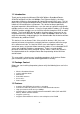
1.1 Introduction Thank you for purchasing Micronet SP916GK Wireless Broadband Router. SP916GK with built-in 4-port 10/100Mbps Fast Ethernet Switch is the latest generation of Wireless router product for Home/Office and SOHO users. This fullfeature and self-contained compact Wireless Router will allow broadband access in both of LAN and Wireless environment. This device has been specifically designed to provide LAN and Wireless users the most cost-effective method with multiple accesses to the Internet.
• • • • • • • • • • • • Provides MAC access control and hidden SSID function WDS supported with WEP, TKIP and AES encryption Channel : USA 11, Europe 13, Japan 14 Supports NAT/NAPT IP Sharing Supports Static IP, PPPoE, PPTP, & DHCP client SPI Anti-DoS Firewall; Virtual DMZ; DNS relay; UPnP Provides DHCP server Supports VPN pass through Supports ALG for FTP, NetMeeting, VPN pass-through, DDNS (DynDNS, TZO) Supports firmware upgrade function via Web Compliant with FCC Part 15.
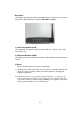
Back Panel The diagram (fig1.0) below shows the broadband router’s back panel. The router’s back panel is divided into three sections, LAN, WAN and Reset: 1) Local Area Network (LAN) The 4 LAN ports are for you to connect to your LAN’s PCs, printer servers, hubs and switches etc. 2) Wide Area Network (WAN) The WAN port is for connecting to your xDSL or Cable modem and is linked to the Internet. 3) Reset The Reset button allows you to do one of two things.
Front Panel On the router’s front panel, there are LED lights that inform you of the router’s current status. Below is an explanation of each LED and what each stands for.
2. Installing and Using Wireless Router This Chapter provides a step-by-step guide to the installation and configuration of the Wireless Router. We suggest you go over the whole chapter before doing more advanced operation. 2.1 Network configuration setup Steps to build up the network: Step1. Connect the ADSL or Cable modem to the Ethernet WAN port on the back of the Wireless Router by using the UTP cable. Step2.
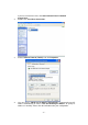
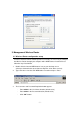
2. If you are in Start menu view, click StartÆControl PanelÆ Network Connections. Double click “Local Area Connection” 3. Choose Internet Protocol (TCP/IP) and click Properties. 4. You may choose “Obtain an IP address automatically” (recommend) to get IP address automatically or choose “Use the following IP address” to specify IP addresses manually. Please click the OK button after your configuration.
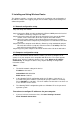
3. Management Wireless Router 3.1 Wireless Router configuration setup In order to make the whole network operate successfully, it is necessary to configure the Wireless Router through your computer with a WEB browser installed. Please follow the steps listed below. 1. Double click the Internet WEB browser icon on your desktop screen (Netscape Communicator 4.0 and Internet Explorer 3.0 or above version) 2. Type 192.168.1.1 into the URL WEB address location and press Enter. 3.
4. The Graphic User Interaface After the password authorization, the Setup Wizard shows up as the home page of the Graphic User interface. You may click on each folder on left column of each page to get access to each configuration page. 3.2 Setup Wizard If you are using the router for the first time, you may follow the procedures of the setup wizard to do a step-by-step configuration. Note: The following instruction does an overall introduction to the Setup Wizard.
2. Select your demanding operation mode and click “Next”. 3. Mark the check box to enable synchronizing time by NTP server. Select the religion you live in and a NTP server by clicking the drop list, then click “Next” 4. Specify an IP address and subnet mask for connecting to the router in LAN.
5. Select a WAN access type for the router to connect to Internet. Fill in the parameters required in each blank, and then click the “Next” button. Those parameters should be provided by your ISP. 6. Select the wireless parameters that are used for associating with this router and click “Next” 7. Click the drop list to select the encryption type for your wireless network. Fill in the parameters for the encryption type you selected and click finish to complete configuration.
3.3 Operation Mode Setup To select an operation mode for this router, click on the mode that you want to perform and click the button to execute.
3.4 Wireless Setup Wireless Access Point builds a wireless LAN and can let all PCs equipped with IEEE802.11b/g wireless network adaptor to connect to your Intranet. It supports WEP encryption and MAC address filter to enhance the security of your wireless network. Basic Setting You can set up the configuration of your Wireless and monitor the Wireless Clients associate with your AP.
Click button at the bottom of the screen to save the above configurations. You can now configure other advanced settings or start using the router (with the advance settings in place) Active Wireless Client Table This is the window that pops up after clicking the “Show Active Clients” button. MAC Address MAC address of this active wireless station. Tx Packet The number of transmitted packets that are sent out from this active wireless station.
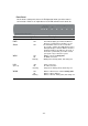
Configuration Open System mode Authentication Type Fragment Threshold RTS Threshold Beacon Interval Data Rate Preamble Type Wireless AP can associate with this wireless router without WEP encryption. You should also set up WEP key in the Shared Key "Security" page. Wireless AP associated with this wireless router mode should use WEP encryption in the authentication phase. The wireless client can associate with Auto this wireless router by using any one of these two Modes.
Broadcast SSID IAPP 802.11g Protection If you enable "Broadcast SSID", every wireless station located within the coverage of this wireless router can find this wireless router easily. If you are building a public wireless network, enabling this feature is recommended. Disabling "Broadcast SSID" can provide better security. Enables multiple AP to communicate and pass information regarding the location of associated Stations. Some 802.11g wireless adapters support 802.
WPA Cipher Suite There are two items, “Enterprise (WPA-Radius)” and “Personal (Pre-Shared Key)”. You can select the mode by clicking the item. Select the WPA Cipher Suite to be TKIP or AES WPA2 Cipher Suite Select the WPA2 Cipher Suite to be TKIP or AES WPA Authentication Mode Pre-Shared key Format To define the format, select what you need in the drop list. Enter the Pre-shared Key according to the prePre-shared Key shared key format you selected.
MAC Address & Comment Current Access Control list device. To set up the Value of MAC Address & Comment; enter the MAC Address and Comment of the station and click Apply Changes to save. To delete the station from the list, click the check box in the select item and click the “Delete Selected”. If you want to delete all stations on the list, click “Delete All” to remove all of them. Click at the bottom of the screen to save the above configurations.
3.5 TCP/IP Setting LAN Interface Setting This sections cover how to set up the configuration of LAN interface, Private IP of you router LAN Port and Subnet mask for your LAN segment. Configuration IP address The IP of your Router LAN port (Default 192.168.1.1) Subnet Mask Subnet Mask of you LAN (Default 255.255.255.0) DHCP Server DHCP Client Range 802.1d Spanning tree Enable UPnP To give your LAN Client an IP, you have to enable “DHCP Server”.
Static IP Mode IP Address, Subnet Mask and Default Gateway Fill in the IP address, Subnet Mask and Default Gateway that provided by your ISP. DNS 1, 2 and 3 To specify the DNS, and enter the DNS provided by your ISP in DNS 1 2 3.
Attain DNS automatically: If your DNS provided by ISP is dynamic, choose “Attain DNS automatically Set DNS Manually To specify the DNS, enter the DNS provided by your ISP in DNS 1 2 3. PPPoE Mode User Name, password and service name Fill in the User Name, password and service name that provided by your ISP. Connection Type “Continuous” is for Always keeping connection Idle Time: MTU Size Attain DNS “Connect on demand” is for billing by connection time.
automatically: “Attain DNS automatically Set DNS Manually To specify the DNS, enter the DNS provided by your ISP in DNS 1 2 3. PPTP Mode IP Address, Subnet Mask, Server IP Address, User Name and Password Fill in the IP address, Subnet Mask, Server IP Address, User Name and password that provided by your ISP. MTU Size Enable the Maximum Transmission Unit of Router. Any packet greater this number will be chopped up into suitable size before sending.
Common configurations for WAN interface Some settings can be configured with each WAN access types: Enable Web Server Access on WAN from port To enable the user to access this Router through Internet, enter the specific IP and the port number Enable IPsec pass through on VPN connection Mark the check box to enable IPsec pass through on VPN connection; clear the checkbox to disable.
3.6 Firewall Configuration Port Filtering The firewall not only can obstruct outside intruders from intruding your system, but also restricting the LAN users. Port Filtering can be used to restrict certain type of data packets from your LAN to Internet through the Router by adding it on the Current Filtering Table. Configuration STEPS 1. Click the check box of “Enable Port Filtering” to enable the function. 2. Enter the Port range (EX 25-110), Protocol (UDP/TCP), and comment (EX. E-Mail) 3.
IP Filtering The Wireless Router could filter the outgoing packets for security or management consideration. You can set up the filter against the IP addresses to block specific internal users from accessing the Internet. Configuration STEPS 1. Click the check box of “Enable IP Filtering” to enable the function. 2. Enter the specific Local IP address (EX 10.10.3.9), Protocol (UDP/TCP), and comment (EX. Peter) 3.
MAC Filtering The Wireless Router could filter the outgoing packets for security or management consideration. You can set up the filter against the MAC addresses to block specific internal users from accessing the Internet. Configuration STEPS 1. Click the check box of “Enable MAC Filtering” to enable the function. 2. Enter the specific MAC address (EX 00:0e:b6:a8:72), and comment (EX. Peter) 3.
Port Forwarding The Port Forwarding allows you to re-direct a particular range of service port numbers (from the Internet/WAN Ports) to a particular LAN IP address. It helps you to host some servers behind the router NAT firewall. Configuration STEPS 1. Click the check box of “Enable port forwarding” to enable the function. 2. Enter the specific IP address (EX 10.10.10.10), Protocol (UDP/TCP), Port range (EX 25-110), and comment (EX. E-Mail) 3.
URL Filtering The URL Filter allows users to prevent certain URL from being accessed by users in LAN. This filter will block those URLs that contain certain keywords. Configuration STEPS 1. Click the check box of “Enable URL Filtering” to enable the function. 2. Enter the URL to be banned. 3. To delete the URL on the table, click the check box in the select item, and click the “Delete Selected”. If you want to delete all URLs on the table, click “Delete All” to remove all of them.
Virtual DMZ The virtual DMZ is used to enable protocols needed to open ports on the router. The router will forward all unspecified incoming traffic to the host specified in this page. Enter the Host IP (private IP address), and click “Apply changes” to activate the setting.
3.7 Management Status In the home page of the Wireless Router, the left navigation bar shows the options to configure the system. In the right navigation screen is the system status summary for viewing the configurations. System Uptime The amount of time that the device is power on. Firmware Version The version of the firmware applied on this device.
network BSSID The Basic Service Set Identity of this router.(This parameter is the same as the MAC address of LAN port) Associated Clients The number of associated clients.
DDNS This page allows users to connect to DDNS. To enable DDNS, mark the “Enable DDNS” checkbox. Select the service provider from the drop list. Fill in domain name, username, and password. Click the “Apply Change” button after configuration. Time Zone Setting This page allows users to configure the time setting of the router. To specify manually, fill in the blanks in “Current Time” and click the “Apply Change” button.
2. To see all information of the system, select the “system all” checkbox. 3. To see wireless information only, select the “wireless” checkbox. 4. To send the log information to a certain note, select the “Enable Remote Log” checkbox and fill in the IP address in the “Log Server IP Address” box. 5. Click the “Apply Changes” button to activate You could also click the “Refresh” button to refresh the log information or click the “clear” button to clean the log table.
Save and Reload Setting To save setting to file, click “Save...” button. To load setting from file, 1. Click “Browse…” to select the file 2. Click upload to start the process and wait for it to complete To reset setting to Default, click reset to start the process, and when completed, the status LED will start blinking. Password To set up the Administrator Account information, enter the Username, New password, and reenter the password on the text box.
Product Specifications Standard Interface WAN Connection Cable Connections Network Data Rate Transmission Mode LED indicators Security Receiver Sensitivity Transmit Power Range Coverage Emission Operating Temperature Operating Humidity Power Supply IEEE802.3, 10BASE-T IEEE802.3u, 100BASE-TX IEEE802.3x full duplex operation and flow control IEEE802.11b wireless LAN infrastructure IEEE802.11g wireless LAN infrastructure 1 * WAN port 4 * 10/100 RJ-45 Fast Ethernet switching ports Antenna: 802.
Appendix A How to Manually find your PC’s IP and MAC address 1) In Window’s open the Command Prompt program 2) Type Ipconfig /all and • • • Your PC’s IP address is the one entitled IP address (192.168.1.77) The router’s IP address is the one entitled Default Gateway (192.168.1.
Glossary Default Gateway (Router): Every non-router IP device needs to configure a default gateway’s IP address. When the device sends out an IP packet, if the destination is not on the same network, the device has to send the packet to its default gateway, which will then send it out towards the destination. DHCP: Dynamic Host Configuration Protocol. This protocol automatically gives every computer on your home network an IP address.
ISP: Internet Service Provider. An ISP is a business that provides connectivity to the Internet for individuals and other businesses or organizations. LAN: Local Area Network. A LAN is a group of computers and devices connected together in a relatively small area (such as a house or an office). Your home network is considered a LAN. MAC Address: MAC stands for Media Access Control. A MAC address is the hardware address of a device connected to a network.
create IP address numbers used only within a particular network (as opposed to valid IP address numbers recognized by the Internet, which must be assigned by InterNIC). TCP/IP, UDP: Transmission Control Protocol/Internet Protocol (TCP/IP) and Unreliable Datagram Protocol (UDP). TCP/IP is the standard protocol for data transmission over the Internet. Both TCP and UDP are transport layer protocol. TCP performs proper error detection and error recovery, and thus is reliable.