
Hardware Guide


z
Rev. 3 Micronet SmartCAM™ - Hardware Guide 36 / 50
8. Signals Map
Overview
This chapter describes the Micronet SmartCAM™ standard and enhanced signal interfaces.
Basic and Intermediate Signal Map
The Micronet SmartCAM™ Basic Model has the following interfaces on its main cable harness which are
soldered directly to the PCB:
• Power Line
• Ground Line
• Digital Input Line
• Open Collector Output
• USB Type-C connector cable to be connected on the computer USB Host connector
• Serial Port and Debug Port with TX, RX, GND signals, baud rate 300-115200bps
The following abbreviations are used:
• I - Input signal
• O - Output signal
• B - Bus signal
• V - Voltage signal
• G – Ground
• P – Positive
• N – Negative
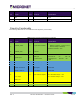
Standard and Intermediate Model Signal Pinout
Pinout by Pin Number
The following table lists the 12 Basic and Intermediate Model signals by pin number: