
Hardware Guide


z
Rev. 3 Micronet SmartCAM™ - Hardware Guide 40 / 50
Pin
Signal
Type
Function
Specifications
15
GPIO
I/O
General-Purpose
Configurable General-Purpose Input /
Output
16
SWC
I/O
Single Wire CAN
Pinout by Functionality
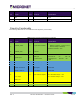
The following table lists the 16 enhanced model signals by functionality:
Table 11: Main Connector Signal Map (by functionality)
Pin
Signal
Type
Function
Specifications
1
POWER_INPUT
V
Input Power 12V/24V
Typical – 12V/24V
- Minimum continues – 6V (5V for up to
40ms according to ISO7637)
Maximum continues – 32V
2
POWER_GND
G
Ground
3
Ignition Input
A
A2D Input
Ignition switch
Typical Min Max
Input Low: VIL 0V -30V 6V
Input High: VIH 12V-24V +8V
+32V
4
CAN 1 H
I/O
CAN 1 High Signal
Twisted Pair
5
CAN 1 L
I/O
CAN 1 Low Signal
Twisted Pair
6
J1708+ or CAN 2 H
I/O
J1708 Positive or CAN 2
High Signal
Twisted Pair
7
J1708- or CAN 2 L
I/O
J1708 Negative or CAN
2 Low Signal
Twisted Pair
8
O.C. Output
O
Open Collector Output 1
Max. switchable current = 300mA
Max. switchable voltage = +VIN
Max. saturation voltage = 0.6V
9
RS232_TX1
I
Transmit Data (COM1)
EIA-RS232 level
10
RS232_TX_DBG
O
Transmit Data DBG
MCU Debug port EIA-RS232 level
11
RS232_RX_DBG
I
Receive Data DBG
MCU Debug Port EIA-RS232 level
12
GND
G
Ground