
Hardware Guide


z
Rev. 3 Micronet SmartCAM™ - Hardware Guide 44 / 50
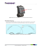
Figure 21: Electrical Installation Scheme
Electrical Installation Procedure
1. Prepare the wiring for power, ground and ignition switch in the vehicle, for connecting to the
Micronet SmartCAM™ cable.
2. The power signal connects to the vehicle's power line protected by a 10A fuse. Add an inline 3A
"Slow Blow" fuse with fuse holder for HHC/HHD blade-type fuses to the power cable.
3. The ground signal connects to the vehicle's ground line.
4. The ignition input signal connects to the vehicle's ignition switch line.
5. Fix the cable after verifying that all the functions are performing properly.
6. Arrange the cables using a plastic strip.
The must be connected to power before inserting the Micronet SmartCAM™ into the cradle. If
the Micronet SmartCAM™ is inserted while the is not connected to power, the Micronet
SmartCAM™ shuts down immediately.