MNL-10Rxx Series MNL-15Rxx Series MNL-20Rxx Series TAC I/A Series MicroNet MN 100, MN 150, and MN 200 Controllers Installation Instructions Application The TAC I/A Series MicroNet™ MNL-10Rxx, MNL15Rxx, and MNL-20Rxx (MN 100, MN 150, and MN 200) Controllers are interoperable devices designed in accordance with LONMARK® guidelines and equipped with LONMARK HVAC profiles. These controllers support MN-Sx digital sensors.
Applicable Documentation F-Number Description Audience Purpose F-26277 TAC I/A Series MicroNet MN-Sx Series Sensors General Instructions – – – – Application Engineers Installers Service Personnel Start-up Technicians Provides step-by-step installation and checkout procedures for TAC I/A Series MicroNet MN-Sx Series Sensors. Also contains instructions for sensor operation.
Precautions General Warning: Electrical shock hazard! Disconnect power before installing or removing the cover. • Follow Static precautions when installing this equipment. • Use copper conductors that are suitable for 167°F (75°C). • Make all connections according to electrical wiring diagram, national and local electrical codes. Static Precautions Static charges damage electronic components. The microprocessor and associated circuitry are extremely sensitive to static discharge.
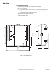
Mounting Panel or DIN Rail Mounting 1. Select mounting location. Enclosure mounting is recommended. 2. Do one of the following: a. Using two #6 pan head screws, mount base of controller to a panel (Figure-1). b. Snap controller base on a 35mm DIN mounting rail (not provided). Multiple units can be mounted side by side on a DIN mounting rail. 3. Wire controller base (See Wiring section). 4. After wiring, insert cover tabs into brackets on base of the controller and gently push until cover snaps into place.
Wiring Review Figures 2, 3, and 4 when making electrical connections to controller. The following electrical connections can be made to the controllers: • Sensor Link (S-Link) connection to TAC I/A Series MicroNet Sensor (MN-Sx). • MicroNet LONWORKS network (LON®) connection. • I/O connections including Universal Inputs, Digital Inputs (MN 100 and MN 200), Analog Outputs (MN 150 and MN 200), and Digital Outputs. • Power connection to a 24 Vac nominal Class 2 power source and earth ground.
Universal Inputs 5 0 to 5 Vdc 0 to 20mA 3 10K Thermistor 6 5 1K Balco 1K Platinum Digital 1 2 Analog Outputs 0 to 20mA into an 80 to 550Ω load Sensor Link Supports 1 TAC I/A Series MN-Sx Sensor LONWORKS Network Communications FT 3150 Transceiver Ul1 COM UI2 COM UI3 AO2 COM AO1 24H 24G GND C1 NO1 C2 NO2 S-LK S-LK LON LON AC Power 24 Vac, 50/60 Hz Class 2 (EN 60742) 15 VA per Controller plus DO load if same transformer is used.
Universal Inputs 5 0 to 5 Vdc 0 to 20mA 3 10K Thermistor 6 5 1K Balco 1K Platinum Digital 1 2 Analog Outputs 0 to 20mA into an 80 to 550Ω load Digital Inputs 1 4 Dry Contact Sensor Link Supports 1 TAC I/A Series MN-Sx Sensor LONWORKS Network Communications FT 3150 Transceiver Ul1 COM UI2 COM UI3 AO2 COM AO1 DI2 COM DI1 S-LK S-LK LON LON 24H 24G GND C1 NO1 C2 NO2 C3 NO3 C4 NO4 C5 NO5 C6 NO6 AC Power 24 Vac, 50/60 Hz Class 2 (EN 60742) 15 VA per Controller plus DO load if same transformer is used.
Communications Wiring Caution: • Communication wire pairs must be dedicated to MN-Sx (S-Link) and MicroNet LONWORKS network (LON) communications. They cannot be part of an active, bundled telephone trunk. • Shielded cable is not required for S-Link or LON wiring. • If the cable is installed in areas of high RFI/EMI, the cable must be in conduit. • If shielded wire is used, the shield must be connected to earth ground at one end only by a 470K ohm 1/4 watt resistor.
I/O Wiring I/O connections include universal inputs, analog outputs, digital inputs, and digital outputs. See Figure-2, Figure-3, and Figure-4 for proper wire terminal information. Caution: If shielded cable is used, connect only one end of the shield to earth ground at controller. Universal Inputs (UI), Analog Outputs (AO), and Digital Inputs (DI) Caution: • Input and output devices cannot share common wiring. Each connected device requires a separate signal and return conductor.
Controller Outputs Controller 4 to 20mA Actuator AO1 + - AO1 COM 0 to 10Vdc 500 COM + - AO2 AO2 Figure-5 Analog Output Connections for 4 to 20mA and 0 to 10Vdc Actuators.
Digital Outputs (DO) Caution: • DO terminals accept one 16 gage (1.29mm) wire or two 18 gage (1.02mm) wires. The selected wire gage must be consistent with the load current rating. • DO wiring cannot be intermixed with DI, UI, S-Link, LON and AO wiring. • MN 100, MN 150, and MN 200 controllers are Class 2 devices. Each digital output can support up to 24 Vac/Vdc at 1.0 amp (24 VA) pilot duty. Note: Digital Output wiring can be intermixed with class 2 power wiring.
Power Supply Wiring Caution: • MicroNet I/A Series Controllers are Class 2 only devices and must be connected to a Class 2 source. Class 2 circuits must not intermix with Class 1 circuits. • This product contains a non-isolated half-wave rectifier power supply and must not be powered by transformers used to power other devices containing non-isolated full-wave rectifier power supplies. Refer to EN-206, Guidelines for Powering Multiple Devices from a Common Transformer, F-26363, for detailed information.
To other MN 100, MN 150, MN 200, MN 440, MN 620 and VAV controllers. Primary To rest of the LONWORKS network. 24 Vac Secondary Class 2 Ground Frame of Transformer to Known Ground MNL-10Rxx MNL-15Rxx MNL-20Rxx 1 Class 2 Wiring 2 Optional connection provides local access to the LONWORKS network. 2 LON 1 S-Link MN-Sx Sensor MNL-10Rxx MNL-15Rxx MNL-20Rxx 2 LON S-Link MN-Sx Sensor MNL-10Rxx MNL-15Rxx MNL-20Rxx 2 LON S-Link MN-Sx Sensor To rest of the LONWORKS network.
Checkout Mechanical Hardware Checkout 1. Verify wiring between TAC I/A Series MicroNet Sensor and controller is installed according to job wiring diagram and national and local wiring codes. Note: Wiring of the S-Link and MicroNet LONWORKS network between the sensor and the controller is not polarity sensitive. 2.
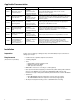
Table-3 LED Indication. Indicator Data Reception LED – amber Context Anytime Status Corrective Action Blinks when the controller receives data from the LONWORKS Network. None required. On indicates a possible network connection problem, or a large amount of network traffic is present. Remove the LONWORKS Network connections from the controller and determine if the LED goes off. If the LED does not go off, replace the controller.
Controller Selection Identical pairs of factory barcode labels are attached to each controller. The labels can be used to select controllers for application downloading purposes. Each pair of labels contains a unique Neuron ID. One of the labels remains on the controller permanently; the other label can be placed on a job site plan. The Neuron ID may be entered into the WorkPlace Tech Tool. The WorkPlace Tech Tool (must be version 4.0 or greater) can then download an application to the selected controller.