
Technical information


F-26266-7 © 2010 Schneider Electric. All rights reserved.. 9
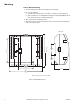
I/O Wiring
I/O connections include universal inputs, analog outputs, digital inputs, and digital outputs.
See Figure-2, Figure-3, and Figure-4 for proper wire terminal information.
Caution: If shielded cable is used, connect only one end of the shield to earth ground at
controller.
Universal Inputs (UI), Analog Outputs (AO), and Digital Inputs (DI)
Caution:
• Input and output devices cannot share common wiring. Each connected device requires
a separate signal and return conductor.
• Power wiring cannot share conduit with UI, AO, S-Link, LON, or DI wiring.
Note:
• If maximum closed switch voltage is not more than 1.0 V and minimum open switch
voltage is at least 4.5 V, then solid state switches may be used for a UI or a DI.
• UI, AO, DI, and S-Link wiring can share a single conduit.
UI, AO, DI, wiring needs at least 24 gage (0.51mm), twisted pair, voice grade telephone wire.
The capacitance between conductors cannot be more than 32 pF per foot (0.3m). If shielded
cable is used, the capacitance between any one conductor and the others, connected to the
shield, cannot be more than 60 pF per foot (0.3m). Table-1 provides wiring specifications.
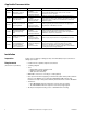
Table-1 UI, AO, and DI Wiring Specifications.
Connection
Gage
AWG (mm)
Maximum Distance
ft. (m)
UI, AO, and DI
18 (1.02) 300 (91)
20 (.81) 200 (61)
22 (.65) 125 (38)
24 (.51) 75 (23)