User’s Manual 8/16-Port Enterprise KVM Switch Model No.: SP218D/SP226D http://www.micronet.
Certifications FCC This equipment has been tested and found to comply with Part 15 of the FCC Rules. Operation is subject to the following two conditions: (1) This device may not cause harmful interference (2) This device must accept any interference received. Include interference that may cause undesired operation. CE This equipment is in compliance with the requirements of the following regulations: EN 55 022: CLASS B.
Table of Contents Chapter 1 Introduction................................................................................... 1 1.1 Package Contents .......................................................................................... 1 1.2 Key Features ................................................................................................. 1 1.3 Specification ................................................................................................. 2 Chapter 2 Hardware Installation......
3.5.6 User Security....................................................................................................16 3.5.7 Access List .......................................................................................................17 3.5.8 Hotkey ...............................................................................................................17 3.5.9 Time Setting .....................................................................................................18 3.5.
Chapter 1 Introduction Micronet proudly introduces SP218D/SP226D, 8/16-Port Enterprise KVM Switch. It is ideal for utilizing server or normal PC for centralized control on a single administrative area. With its high port quantity, it can easily scale up to enterprise level network environment. It provides both PS/2 and USB connectors for mouse and keyboard usage (Convert PS/2 to USB via convert connector). The KVM switch provides OSD and hotkey control to allow users to operate the device without hassle.
y y y y y 1.
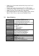
Chapter 2 Hardware Installation 2.1 Physical Description 8-Port Front View 16-Port Front View 8-Port Rear View 16-Port Rear View 2.1.1 Front LED LED Status Online Red/On Select Blue/On Bank Bank No./On Operation On to indicate that a PC is successfully connected to the KVM. On to indicate the selected PC on the local monitor. Indicates bank number of the device (Useful for Daisy Chain connection). 2.1.
y 2.2 Daisy Chain: For connecting multiple KVM together. Cable Diagram 2.2.1 3-in-1 DB15 Cable One end, HDDB15 (male) connectors with another end HDDB15 (male)/ two PS/2 (mini-din 6-pin) connectors. 2.2.2 PS/2 (keyboard) to USB adapter PS/2 (keyboard) to USB (keyboard and mouse) adapter. 2.2.3 Daisy Chain Cable VGA Cable: HDDB15 Male to Male. Daisy chain needs the cable all 15 lines connected. This is a special VGA cable, normal VGA cable has unconnected lines.
2.3 Rack Mount Installation Before installation, please make sure all of peripherals and computers have been turned off. Find a convenient place to put your KVM Switch. The 19” rack mount form factor makes it ideally mountable on a 19” rack. When mounting to a rack, attach the included brackets to the sides of the KVM Switch. Take note of the length of your cables so that your computers, KVM Switch, keyboard, mouse and monitor are distanced properly.
2.4 3-in-1 HDB15 Cable Installation On the back of the KVM Switch, each of the 8 /16 PC ports has a HDB15 type connector. Each cable that comes with the Switch has a 3-in-1 connector at one end and a single HDB15 male connector at the other end. Plug the single connector end of the cable into the KVM PC port, and then plug the other end of cable to a PC VGA port. PS/2 computer --- Plug in the PS/2 mouse connector to the computer mouse port, then the PS/2 keyboard connector to computer keyboard port.
2.5 Installation Steps Follow the steps below to setup the hardware: y Plug the 3-in-1 end of the KVM cable to the PC. Connect the HDB-15 connector to PC’s VGA port. Attached the PS/2 connector for both mouse and keyboard to PC’s PS/2 ports. y For PC with USB port, use a PS/2 to USB converter to switch between interfaces and connect via PC’s USB slot. y Then connect the other end of the 3-in-1 cable with only a single HDB-15 connector to the PC port on the rear of KVM.
y 2.6 into the electrical receptacle. Now you will see the LED of Port 1 lights up, and hear a beep sound. Recommended Power On sequence: Monitor, KVM then PC. Daisy Chain Connection Connecting multiple KVM together, please use a daisy chain cable (sold separately) to connect via the Daisy Chain port and Local Console’s VGA port.
Chapter 3 Operation 3.1 Push Button Users can simply switch to a port by pressing the corresponding push button on the LED. For 8 ports KVM Switch, please press button 1 ~ 8 directly to select the port you want. For 16 ports KVM Switch, please press “Shift” button and individual button 1~8 simultaneously to switch to the port from port 9 to port 16. For example: Pressing “shift” button and 5 simultaneously to switch to port 13, and the port red LED will turn on.
3.3 Hot Plug The KVM Switch supports “Hot Plug” function for any non-PS/2 connectors. Users may Hot Plug the USB mouse or USB keyboard. y y 3.4 DO NOT hot plug PS/2 port. Certain Operation Systems like SCO Unix or Linux does not support “Hot Plug” function. If users apply “Hot Plug” to this kind of O.S., it will cause unpredictable behavior or shut down the Computer. Before attempting to use “Hot Plug”, please make sure Operation Systems and mouse software driver support the “Hot Plug” function.
¾ First digit refers to the bank numbers used for identifying each KVM in multiple device connections. The last two digits represent the port for each PC connected to the KVM switch. 3. The OSD interface can also be accessed via Mouse: ¾ Press and hold the left button of the mouse and hit the Esc key to show the Status screen. ¾ Press and hold the right button of the mouse and hit the Esc key to bring up the Main Menu. 3.4.
This OSD Menu has four types of display screens: 1. Login Window - When powering on this KVM switch, it will prompt a login window and ask for user name and password. This KVM system can setup one SUPERVISOR and eight USERS. SUPERVISOR can access to all OSD functions. USER can access to PORT NAME and PORT SEARCH only. 2. Status screen - After the logging in, the Status screen will show up to display the current port settings and Hotkey type. 3.
3.5.1 Login Window If the Security function is enabled (default is disabled), the Login window will show up waiting for username and password when device powers on. Parameter SUPERVISOR Username SUPERVISOR Password Default 00000000 (Eight Zeros) 00000000 (Eight Zeros) These values are case-insensitive, while OSD display fixed in upper case. After login or port switch by panel button, OSD or Hotkey, the Status screen will show up to display the information of current settings.
3.5.2 Port Name The first page shows the current port name, the selected port, and the operation hint. Command F1 F2 F3 Enter ↑/↓ PgUp PgDn Esc 1 2 3 4 y Description Go to the Main Menu. Logouts of the OSD. If Security is enabled it will show up the Login window waiting for username and password. If Security is disabled it will show the Status window.
3.5.3 Language The OSD supports eight languages: English, French, German, Italian, Spanish, Simplified Chinese, Japanese, and Russian. The default language is ENGLISH. Moving the cursor by keyboard (Up Arrow key or the Down Arrow key) or mouse to select the language you like. 3.5.4 PORT NAME EDIT The first line bar is Bank number, following lines are port name list. Use keyboard (Up Arrow key or Down Arrow key) or mouse to select the port.
3.5.5 Port Search Search the computer by port name. Enter “*” will show all the port names. 3.5.6 User Security There are two types of user levels: SUPERVISOR and USER. There is one SUPERVISOR and up to eight USERS can be configured. Press the key or right button of mouse for editing. The left-top “S” means SUPERVISOR, and “1”, “2”, “3”,…., “8” means USERS. The maximum length of NAME and PASSWORD is eight characters (A~Z and 0~9).
3.5.7 Access List Only SUPERVISOR can configure the ACCESS LIST. The first column is the port number, following the server/computer name list. The last 8 columns are the access right of each user. Use the key or left button of mouse to active/deactivate the access right of each port. “X” means to disable access and “O” means to enable access. 3.5.8 Hotkey Some keyboard may not equip with all the special keys. Make sure the key select is available on the keyboard.
3.5.9 Time Setting When the Auto-Scan function is activated, the KVM switch will auto-scan the host ports one by one according interval setting. Notice that the port without connecting to a computer/server will be skipped on the scan. The interval range is 5 ~ 99 seconds, and the default interval is 10 seconds. Press key to save the SCAN TIME setting. 3.5.10 OSD Mouse Users can change the moving speed of mouse cursor in this item. There are three levels to choose from.
Chapter 4 Troubleshooting y No LED display ¾ Make sure the power adapter is correctly plugged into the KVM Switch. If the LED’s still won’t light, perform soft reset to KVM switch by pressing “BANK” button and last port button at the same time. ¾ Do the hard reset by unplugging the power then plugging in again. y The computer boot up fine, but keyboard doesn’t work ¾ PS/2 keyboard or PS/2 mouse port is not designed for Hot Plug.
information that causes the VGA resolution output mismatch with the monitor’s. ¾ In this case, please turn off the PC wait few minute then turn on again. y Micronet provide tech support ¾ You can find related information from web site www.micronet.info. ¾ Any question about Micronet KVM product, please send mail to support@micronet.info.