User's Manual Wireless LAN Bridge Model No.: SP912 World Wide Web: www.micronet.com.tw ; www.micronet.
Table of Contents Chapter 1 Introduction............................................................................................................ 1 1.1 Features and Benefits........................................................................................................ 1 1.2 Package Contents .............................................................................................................. 2 1.3 Applications ............................................................................
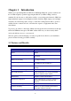
Chapter 1 Introduction Thank you for purchasing Micronet Wireless LAN Bridge SP912. It operates seamlessly in the 2.4 GHz frequency spectrum supporting the 802.11b (2.4GHz, 11Mbps) wireless standards. It's the best way to add wireless stable to your existing wired network. SP912 has high transmitted output power and high receivable sensitivity. High output power and high sensitivity can extend range and coverage to reduce the roaming between APs to get more stability wireless connection.
1.2 Package Contents Open the package carefully, and make sure that none of the items listed below are missing. Do not discard the packing materials, in case of return; the unit must be shipped in its original package. h h h h h One SP912 unit One Omni directional Antenna One Power Adapter One Quick Installation Guide One CD-ROM with User’s Manual Included 1.3 Applications The wireless LAN products are easy to install and highly efficient.
Wireless extensions to Ethernet networks Network managers in dynamic environments can minimize the overhead caused by moves, extensions to networks, and other changes with wireless LANs. Wired LAN backup Network managers implement wireless LANs to provide backup for mission-critical applications running on wired networks. Training/Educational facilities Training sites at corporations and students at universities use wireless connectivity to ease access to information, information exchanges, and learning.
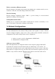
Infrastructure Mode The infrastructure mode requires the use of an access point (AP). In this mode, all wireless communication between two computers has to be via the AP. It doesn’t matter if the AP is stand-alone or wired to an Ethernet network. If used in stand-alone, the AP can extend the range of independent wireless LANs by acting as a repeater, which effectively doubles the distance between wireless stations. The image below depicts a network in infrastructure mode.
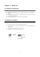
Chapter 2 Hardware 2.1 Hardware Configuration RJ-45 Ethernet Connector – Provides 10 Mbps connectivity to a wired Ethernet LAN. Reset Button – By holding this down for more than five seconds, the unit will reset to its factory default settings. Power Supply Connector – Connects to the power adapter. 2.2 Hardware Installation A. B. C. D. Configure your notebook or PC with a wireless LAN card. For a wired LAN, connect your PC’s Ethernet port to the unit’s LAN port via an Ethernet cable.
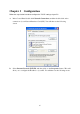
Chapter 3 Configuration Follow the steps below in order to configure the TCP/IP settings of your PC. A. In the Control Panel double click Network Connections, and then double click on the connection of your Network Interface Card (NIC). You will then see the following screen. B. Select Internet Protocol (TCP/IP) and then click on the Properties button. This will allow you to configure the IP address of your PC. You will then see the following screen.
C. D. Select Use the following IP address radio button, and then enter an IP address and subnet mask for your PC. Make sure that the device and your PC is on the same subnet. Click on the OK button, your PC’s TCP/IP settings have been configured.
Chapter 4 Switch Between Access Point & Bridge This chapter describes the steps to switch from Access Point to Bridge, and Bridge to Access Point. This device can be configured as an Access Point or a Bridge. By default, this device is configured as an Access Point, and the default IP address is 192.168.1.1. 4.1 Access Point to Bridge Step1: Enter the default IP address of the Access Point into the address bar of the web-browser (192.168.1.1).
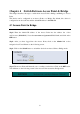
4.2 Bridge to Access Point Step1: Enter the default IP address of the Bridge into the address bar of the web-browser (192.168.1.1). Leave the user name and password fields blank, and click on the OK button. Step2: After you have logged into the Bridge, click on the Admin link on the navigation bar. You will then see the following screen. Step3: Click on the Switch button to switch the device from Bridge to Access Point mode. Step4: The Bridge will then ask to you confirm your decision.
Chapter 5 Access Point – Web Configuration 5.1 Logging In To configure the Access Point through the web-browser, enter the IP address of the Access Point into the address bar of the web-browser (default IP: 192.168.1.1), and press Enter. You will then see the login window. Leave the User name and the Password field blank, and then click on the OK button. You may change the user name and password after you login. In order to do so, refer to section 5.5 Admin.
5.2 System The System page is the first page that is displayed after logging in. This page displays information about the Access Point. You may refresh this page by clicking on the System link on the left-hand side of the page (image left). Described below is the information listed along with an image. AP firmware: displays the version of the firmware installed on the Access Point. WLAN Primary firmware: displays the primary firmware of the wireless LAN card inside the Access Point.
5.3 Wireless Click on the Wireless link on the navigation bar in order to configure the wireless settings of Access Point. The page displays the current wireless settings and allows you to make changes as you choose. Described below along with an image are details on how to configure the wireless settings of the Access Point.
Access Point name: enter a name for the Access Point. The SSID: displays the SSID of the Access Point. The SSID is a unique name shared among all points in your wireless network. The SSID must be identical for all points in the network, and is case-sensitive. Leaving this field blank means using the SSID “any” and connecting to an Access Point with the strongest available signal.
select the default (automatic) to let the Bridge decide which data rate to use. Preamble Type: select a preamble type from the drop-down list, options available are: long, short, or both. Visibility Status: select Visible or Invisible. If Invisible is selected, the Access Point is protected from a discovery or site survey, and all wireless clients must specify the SSID to associate with the Access Point.
Multicast PM buffering: enabling this function can avoid network congestion when there are too many clients to transmit data simultaneously. Click on the Save button to confirm the changes. 5.4 Filtering Click on the Filtering link on the navigation bar in order to configure MAC address filters.
5.5 Admin Click on the Admin link on the navigation bar in order to configure the user name and password to log into the device. You may also reboot this device and reset the setting back to the factory defaults. Described below along with an image are details on how to configure the administrative settings. IP Address Mode: select Static or DHCP. If you select Static, you are required to enter a default IP address, subnet mask, and gateway.
Administrator password: type in the new password into this field, and re-enter it for confirmation purposes in the field below. Isolation: select Enable or Disable. By enabling this feature, wireless clients associated with the Access Point will be able to connect to each other. Allow upgrade uploads: this Bridge can be upgraded via TFTP, therefore place a check in this box if you would like to upgrade this device.
Chapter 6 Bridge Mode – Web Configuration 6.1 Logging In To configure the Bridge through the web-browser, enter the IP address of the Bridge into the address bar of the web-browser (default IP: 192.168.1.1), and press Enter. You will then see the login window. Leave the User name Password fields blank, then click on the OK button. You may also change the password after you login. In order to do so, refer to section 6.5 Admin. After you login, you will see the following screen.
6.2 System The System page is the first page that is displayed after logging in. This page displays information about the AP and Bridge. You may refresh this page by clicking on the System link on the left-hand side of the page (image left). Described below is the information listed along with an image. Connected to SSID: displays the SSID of the Access Point. The SSID is a unique name shared among all points in your wireless network.
Results of the most recent scan: these are the results of a site survey and display the SSID, MAC address, channel number, signal strength, and mode of Access Points of Stations in the area. 6.3 Wireless Click on the Wireless link on the navigation bar in order to configure the wireless settings of this Bridge. The page displays the current wireless settings and allows you to make changes as you choose.
among all points in your wireless network. The SSID must be identical for all points in the network, and is case-sensitive. Leaving this field blank means using the SSID “any” and connecting to an Access Point with the strongest available signal. Channel: select a channel from the drop-down list, which is the shared channel among all points in a point-to-point mode. The permissible channels depend on the regulatory domains.
6.5 Admin Click on the Admin link on the navigation bar in order to configure the threshold values and login details. You may also reboot this device and reset the setting back to the factory defaults. Described below along with an image are details on how to configure the administrative settings. IP Address Mode: select Static or DHCP. If you select Static, you are required to enter a default IP address, subnet mask, and gateway.
Default subnet mask: enter the subnet mask for this Bridge. Default Gateway: enter the IP address of the default gateway. Device Name: enter a name for this Bridge. This field is optional. Allow upgrade uploads: this Bridge can be upgraded via TFTP, therefore place a check in this box if you would like to upgrade this device. It is recommended that this box is unchecked during normal operation, when it does not need to be upgraded.
Appendix A Specifications Model SP912 Standard IEEE 802.11b compliant LAN Port One 10Base-T RJ-45 LAN Port Radio Modulation DSSS Frequency Band 2.4 GHz Data Rate 11, 5.5, 2 and 1 Mbps, Auto Fall-Back Output Power (Max) 23 dBm Security MAC address filtering (AP Mode), WEP Encryption (64/128 bit), Hide SSID in beacons, and Wireless Isolation in AP Mode Operation Channel 11/N.