OWNERS MANUAL MODEL 201 MICROPHONE PREAMPLIFIER PO Box 204 Boulder, CO. 80306 303.443.7454 fax: 303.444.
TABLE OF CONTENTS I. OPERATION . . . . . . . . . . . . . . . . . . . . . . . . . . . . . . . . . . . . . . . . . . . . . . . . . . . 2 A. FRONT PANEL CONTROLS . . . . . . . . . . . . . . . . . . . . . . . . . . . . . . . . . . . . . . . . . . . . . . . . 2 1. GAIN CONTROL ........................................................ 2 2. TRIM CONTROL ........................................................ 2 3. PHANTOM POWER . . . . . . . . . . . . . . . . . . . . . . . . . . . . . . . . . . . . . . . . . .
Thank you for purchasing the Grace design model 201 microphone preamplifier. It is built to be completely reliable and easy to use. However, there are some important instructions included in this manual. Please take the time to familiarize yourself with the installation and operation of the unit and most problems will be avoided. Regardless of what sources you plan to record, the model 201 will be the invisible link between the microphone and recorder.
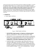
off, the LED will illuminate if voltage is being fed from an external source. (i.e. when using a direct split in a remote recording application.) 4. PHASE REVERSE The phase reverse switch (labeled ∅ ) reverses the absolute polarity of the music signal at the input of the preamplifier. The switch illuminates green and provides power for a sealed gold contact relay located on the preamplifier circuit board. This eliminates signal wiring to the front panel and switch contact performance problems. 5.
level before the trim control, preamplifier overload can be avoided. It is best to leave the trim control fully clockwise for normal recording operations. II. INSTALLATION A. AUDIO TERMINATIONS 1. Input connections are made via female XLR connectors with pin 2 positive, pin 3 negative and pin 1 ground. 48V phantom power is supplied on pins 2 and 3. 2. Output connections are made via male XLR connectors with pin 2 positive, pin 3 negative and pin 1 ground.
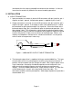
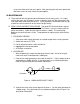
RECORDER END PREAMP END 2 1 1 2 301 3 3 Figure 2. 600Ω BALANCED CABLE TERMINATION B. POWER TERMINATION 1. A standard AC power cable is included. For safety, it is recommended that the cord be connected to a grounded outlet. In the event of noise from a ground loop, the audio ground can be isolated from the chassis ground by throwing the AUDIO GND switch on the rear panel of the preamplifier. (See paragraph 3) 2.
screws that hold each rack ear in place. After removing the rack ears replace the two lower screws on each side of the preamplifier. III. MAINTENANCE A. The model 201 was designed to be maintenance free for many years. It is highly unlikely that your unit will require service. However, there are two adjustments that may need to be made from time to time. These procedures should be made only by a qualified service technician or the Grace Design factory. B.
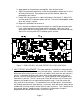
iv. Apply power to the generator, preamplifier, then the level meter. v. Adjust the generator output level so that the preamplifier output level is at the desired red threshold. If the proper level can't be reached, adjust the preamplifier gain control. vi. Locate VR1 on the channel 1 audio circuit board. (See figure 7) Adjust VR1 until the peak LED is between green and red. The color should appear amber when the setting is correct. vii. Repeat this procedure for channel 2. viii.
1. EQUIPMENT NEEDED i. ii. iii. iv. Oscilloscope with a DC coupled 10mV input range. Unbalanced output cable. (see Figure 1.) Plastic alignment tool or a small screwdriver. #2 Phillips screwdriver 2. PROCEDURE i. Remove the 12 #6-32 flat head screws from the top lid but leave the lid in place. ii. Set all of the preamplifier gain controls to minimum. Set the trim controls to maximum. Turn on the 201 preamplifier and the oscilloscope and allow to warm up for at least 45 minutes. iii.
IV.SPECIFICATIONS FREQUENCY RESPONSE @ 40dB gain /± 0.2dB @ 40dB gain /± 3dB 20Hz-300kHz 4.5Hz-1.0MHz THD+N @ 40dB gain +20dbu out <.0015% INTERMODULATION DISTORTION @40dB gain +25dBu out <.0025% NOISE - REFERRED TO INPUT @60dB gain 50 Ω source -130dB PHASE DEVIATION 50-20kHz <2° CROSSTALK @40dB gain -109dB CMRR @60dB gain, 3.5Vcm, 1kHz @60dB gain, 3.