MICROSENS 19'' 6U Chassis Overview 6U Chassis is a part of MICROSENS 10G Transport Platform, a high performance and flexible carrier-class transmission system. The 10G Transport Platform enables increasing transport capacities in CWDM, DWDM and SDH networks. The use of wide range TDM modules permits to reduce the number of necessary wavelengths and to decrease the overall cost of the application. Ethernet over SDH modules enable using existing SONET/SDH infrastructure for IP transmission.
19'' 6U Chassis page 2/71 Introduction The MS430502M chassis which is capable of hosting up to ten aggregation and transport MS modules.
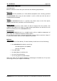
19'' 6U Chassis page 3/71 Figure 1: Management cards and generic slots organisation. The ten additional generic slots available in the MS430502M chassis are capable of hosting various types of aggregation and transport MS modules. The left MGNT board can manage the 5 first generic slots (left slots) of the MS430502M chassis and monitor the FAN tray. The right MGNT board can manage the 5 last generic slots (right slots) of the MS430502M chassis.
19'' 6U Chassis page 4/71 Figure 2: MS430502M chassis General Block diagram. MGNT Management Unit The block diagram of the MGNT unit is given in Figure 3.
19'' 6U Chassis page 5/71 The main characteristics of the MGNT management unit are: • Processor: 32 bit, 177 MHz • RAM memory: 64 Mbytes • Flash memory: 32 Mbytes • Operating System: Linux Figure 3: Management board block diagram. FAN The FAN hosts six separate fans, each of which generates a fan failure signal in event no rotation. These six fans are located on the front panel of the FAN module and organised as following: Figure 4: FAN module organisation. The FAN hosts three power converters.
19'' 6U Chassis page 6/71 If a failure occurs on one of the two main power converters, it is detected by a failure circuitry and the protection power converter is switched on. At the same time an alarm is generated allowing scheduling a preventive maintenance action for replacing the fan unit. When the two main power converters are in fail condition, the protection power converter powers the fans number 1, 3 and 5. The FAN module is monitored by the mandatory management board plugged in slot 1.
19'' 6U Chassis page 7/71 Interface Specifications Power Supply DC input power range: nominal: -36V maximum: -72V MS430502M chassis equipped with AC Power supply are all shipped with 1.25A fuse. Ethernet/ SNMP Ethernet 10/100BASE-T interface SNMP v2c over UDP transport. CLI Port RS232 interface with the following parameters: Parameter Value Bit rate 38400 bits/s Data width 8 Parity None Stop bits 1 Flow control Hardware Mechanical Description Figure 6: MS430502M chassis front view.
19'' 6U Chassis page 8/71 Figure 7: MS430502M chassis mechanical dimension (ETSI flange). Figure 8: MS430502M chassis mechanical dimension (19'' flange). MICROSENS GmbH & Co. KG - Küferstraße 16 - 59067 Hamm - Tel. +49 2381/9452 0 - Fax 9452 100 - www.microsens.
19'' 6U Chassis page 9/71 Installation Manual Site Preparation. Before installation ensure that your site meets the following requirements: Mounting With the mount kit provided, use a 19in (48.3cm) equipment rack, correctly grounded and secure. The MS430502M chassis may also be installed in a 23in or ETSI rack with the aid of suitable extension brackets. Access Locate the MS430502M chassis in a position that allows access to the front panel, enabling maintenance, connection and visual checking.
19'' 6U Chassis page 10/71 Figure 9: MS430502M chassis Front view. Installing the MS430502M chassis Rack mount Installation Securely attach one rackmounting bracket on each side of the front of the chassis with the provided screws. Align the mounting holes in the brackets with the holes in the rack and secure using the remaining screws in the supplied kit. Powering up There are two power inlets to enable backup in case of failure. The second connection is optional.
19'' 6U Chassis page 11/71 Figure 10: Ground screw location. • Connect the cable(s) provided to a correctly protected -48V supply. Fuse Rating: 2.5A, as follows: • Blue - 0V Battery Brown - -48V Connect the other end to the power unit on the front panel of the MS430502M chassis. During the powering up sequence the HW led on the front panel of the MS430502M chassis will momentarily flash green before remaining on.
19'' 6U Chassis page 12/71 Preventive Maintenance Dust Filter replacement Procedure The dust filter should be visually examined on a six month basis.
19'' 6U Chassis page 13/71 MGNT boards are shipped with the Agent software loaded. Note the version required on your site in the case where the replacement board needs to be upgraded follow the procedure: SNMP Agent Update outlined in the MS430502M chassis user manual.
19'' 6U Chassis page 14/71 The rescue CLI allows the user to perform all the upgrade procedure described in the CLI documentation. Use the following procedure to start the rescue CLI on the MGNT management board: Procedure • Use a needle-like tool (i.e. paper clip) to reach the MGNT reset button and press during 5 seconds minimum to activate the rescue CLI feature • Observe behaviour of MGNT LEDs.
19'' 6U Chassis page 15/71 FAN Fan Unit The following alarms indicate a problem with the Fan Unit: • mgnt2AlmFansFailure This bit indicates a failure on one of the fans (General) • mgnt2AlmPbFan1Fail This bit indicates a failure detected on Fan N°1. • mgnt2AlmPbFan2Fail This bit indicates a failure detected on Fan N°2. • mgnt2AlmPbFan3Fail This bit indicates a failure detected on Fan N°3. • mgnt2AlmPbFan4Fail This bit indicates a failure detected on Fan N°4.
19'' 6U Chassis page 16/71 Module maintenance Module Replacement Procedure Use the following procedure to replace a MS module: This procedure is the same for all the MICROSENS module. All the OIDs given in the following procedure are dedicated to the MS43062XM replacement. These OIDs must be adapted to fit the module to replace. Procedure • Ensure that the correct module is selected for management. Consult the object: mgnt2GigmSelectedBoard Location: ...
19'' 6U Chassis page 17/71 ms43062XMRinvSfpTable Location: ...\microsens\modulems43062XM\ms43062XMri\ • Use you SNMP browser to check if there is a backup file linked to the MS module using the object: mgnt2CnfManageConfigFilesTable Location: …\microsens\mgnt2\mgnt2ConfigManagement • If necessary (i.e. if the backup file is absent), create a backup file setting “on” the object: mgnt2CnfBackupConfig associated with the slot number where the MS module is being replaced.
19'' 6U Chassis page 18/71 SFP Replacement Procedure on MS43062XM Each Client port has its own LED located on the front panel of the MS module to indicate operating status of each of the ports. If a client port SFP needs to be replaced use the following procedure. Procedure The SFP ’s are hot-swappable therefore there is no requirement to power down the Module. • Ensure that the correct module is selected for management. Consult the object: mgnt2GigmSelectedBoard Location: ...
'' 6U Chassis page 19/71 • Clean Fibre Optic connectors on fibre optic cable • Re-connect Fibre • Verify correct operation of the SFP End procedure SFP Replacement Procedure on MS430601M and MS430605M Each client port has its own LED located on the front panel of the MS module to indicate operating status of each of the ports. If a client port SFP needs to be replaced use the following procedure. Procedure The SFP ’s are hot-swappable therefore there is no requirement to power down the Module.
19'' 6U Chassis page 20/71 ...\microsens\moduleMS430601M\ms430601mcontrolsWrite\ms430601mCtrlLine\ ms430601mCtrllineSfpOnOffCtrlTable\ • Remove the Fibre Optic connector • Release the SFP by: Carefully opening the latch or pressing the locking button and slide the SFP out of the module and place it aside • Gently push the SFP into the relevant module port until it is securely seated.
19'' 6U Chassis • page 21/71 Check the inventory to verify type of XFP currently installed. Consult the object: ms43062XMRinvXfp Location: ...\microsens\ moduleMS43062XM\ ms43062XMri\ • Take the necessary steps to minimise the impact on your network, traffic bypass re-route etc.
19'' 6U Chassis page 22/71 SNMP User Manual Initial Set-Up and Configuration Configuration Connecting to the manager The MS430502M chassis contains an on-board SNMP agent which allows it to be managed from any point in your network using network management software. Access is via the RJ45 10 Mbit Ethernet port on the front panel. It is necessary to have the latest compiled MiB. Verification of the connection can be achieved by sending a “ping” message to the IP address of the MS430502M chassis.
19'' 6U Chassis • page 23/71 Automatic with DIP switches The MS430502M chassis MGNT Management Board is equipped with 8 DIP switches that may be used to define the MS430502M chassis IP Address. The following picture gives the location of these DIP switches on the Board. Figure 13: MGNT Board top view The DIP switch can be used to set the last byte of the MS430502M chassis IP Address. The right switch is the Most Signficant Byte of the byte and the left switch is the Least Significant Byte of the byte.
19'' 6U Chassis page 24/71 To the value xxx.yyy.zzz.1, where xxx.yyy.zzz defines the MS430502M chassis IP Address map. 2. Configure the DIP switches • Remove MGNT board (see the MS430502M chassis Maintenance manual for details about the unit extraction) • Using the top view of the MGNT Board given previously in this part, locate the DIP switches • Use a needle-like tool (i.e.
19'' 6U Chassis page 25/71 performed using a ping function. The estimated time to detect a dead gateway is less than 30 seconds. The table • mgnt2GigmGatewayAddressTable Location: ...\microsens\mgnt2\mgnt2SNMPAgentData\mgnt2IPmanagment Contains the following objects • mgnt2GigmGatewayAddress • mgnt2GigmGatewayOrder These two objects allow the user to define two different gateways and their order.
19'' 6U Chassis page 26/71 The object mgnt2GigmRwCommunity is not readable. The returned value is always “*******”. • mgnt2GigmTrapCommunity, defines the SNMP Trap community Location: ...\microsens\mgnt2\mgnt2SNMPAgentData\mgnt2Gigmsecurity A warm reset of the MGNT board is necessary to apply the new communities. Management Inventory An inventory check on the system returns the values of the following objects. mgnt2RinvHwPlatform Chassis management module: HW inventory.
19'' 6U Chassis page 27/71 Version Number: 06 Release date (yymmddww):06101241 mgnt2RinvLinux Agent identification. Example Response: Linux Part Number: 3SW06000ACAC Version Number: 01 Release date (yymmddww):06092138 Location: ...\microsens\mgnt2\mgnt2RemoteInventory Alarms In order to retrieve Alarm status information a polling mechanism must be put in place. The appearance of a trap message signals the occurrence of an Alarm. Location: ...
19'' 6U Chassis page 28/71 mgnt2AlmMsSlot6Absent MS present in Chassis slot 6: This OID indicates the presence of a MS modulein Slot 6 of the Chassis. Verify correct configuration. mgnt2AlmMsFanAbsent FAN module present in Chassis: This OID indicates the presence of the FAN module in the Chassis Insert a FAN in the MS430502M chassis mgnt2AlmPbFan1Fail Fan unit n°1 failed on Fan module: This OID indicates a failure on fan 1. Removal of the fan unit or no rotation sets the OID.
19'' 6U Chassis mgnt2AlmLog80Full page 29/71 file must be cleared to insure correct log function function Log File Full Warning : This OID indicates that a log file is 80% full. Check the log files Table :1 MGNT Alarms list Traps A trap is an unsolicited, asynchronous event that the MS430502M chassis generates to indicate a status changes; e.g.: a trap is generated on the detection of a start of an alarm and an end of an alarm.
19'' 6U Chassis Name page 30/71 Description Value DEF_API_OK Default Value 0 DEF_API_COLD_RESET_MODULE Cold Reset request 4 DEF_API_WARM_RESET_MODULE Warm Reset request 5 DEF_API_DOWNLOAD_IN_PROGRESS Download in Progress 3 moduleNotResponding A timeout occurred on requested response of a command 128 messageFormatError The module has detected a wrong message format 129 cmdExecutionError Internal module error during the processing of a message 130 unknownArticleError The article is un
19'' 6U Chassis page 31/71 Software Management MIB location: ...\microsens\mgnt2\mgnt2SoftwareManagement\ In all the following procedures, the user has the possibility to delete some files from the FLASH and/or the RAM memory. It is necessary to delete only one file at a time to ensure a correct delete process. Upgrade Procedures SNMP Agent Update on MGNT A user may update the on-board SNMP agent from the manager. To achieve this, you will need: An SNMP V2C browser.
19'' 6U Chassis page 32/71 When renaming the package ensure that the new name is compliant with the Unix standard and no more than 24 characters long including the extension. • Use your SNMP browser to perform a table update and check the status of the RAM using the table: mgnt2DwlUploadingTable Location:...
19'' 6U Chassis page 33/71 And which one is currently being extracted by the variable: mgnt2ExtractedPack • Check the presence of the required package in RAM Using your SNMP browser perform a table update and consult the table: mgnt2DwlUploadingTable If at this stage there are any problems with the package in RAM, name etc., it can be erased by setting the value: mgnt2DeletePackageFromRam to “ON”. This allows the selected package to be erased from the RAM without affecting the other table values.
19'' 6U Chassis • page 34/71 Progress indicator: The value of: mgnt2PackageExtractionInProgress Can be consulted to monitor the progress of the procedure. It is “on” during extraction and returns to “off” on completion of the operation. After this operation, the SNMP agent is updated, however it is necessary to reboot in order for the system to start using this new version. • Reset. See; Resets in Software Management Section.
19'' 6U Chassis page 35/71 Procedure 1. Remote Loading Phase The object of this phase is to load the software package into the RAM of the MS430502M chassis MGNT. There are no service implications during this phase. For this example, the package will be called package1.pak Preparation • Verify that the package you intend to download into the FLASH is not already there: • Consult the table: mgnt2DwlPackageTable Location:...\microsens\mgnt2\mgnt2SoftwareManagement.
19'' 6U Chassis • page 36/71 Check that your package is loaded correctly by consulting the table: mgnt2DwlUploadingTable Location: ...\microsens\mgnt2\mgnt2SoftwareManagement and verify that the value of: mgnt2DwlUploadFileName is that of your package. Your package is now in the RAM and ready for transferring to the FLASH. In the event of an incorrect completion of this phase see Fall Back 1 for reverse procedure.(Fall Back Procedures) 2.
19'' 6U Chassis page 37/71 In the event of an incorrect completion of this phase see Fall Back 2 for reverse procedure. (Fall Back Procedures) 3. Installation Phase The object of this phase is to install the previously transferred software package, and make it available to the system. There are no service implications during this phase.
19'' 6U Chassis page 38/71 Associated with the package to be erased. If the package that you intend to erase from the FLASH is in use, i.e.: mgnt2ExtractedPack = "two", this operation will have no effect. Erasure of a package in use in prohibited. End procedure Generic slot MS Module Code Update A user may update the MS Module Code, Software or Gateware, remotely. To achieve this you will need: An SNMP V2C browser. (For reading and updating values in the MIB) A tftp client.
19'' 6U Chassis page 39/71 T:\home\> tftp -i 192.168.16.123 PUT xxx.ext /tftpboot/yyy.ext Where: T:\home – is the location of the code on your PC xxx.ext - is the name of the code you wish to upload and yyy.ext - is the new name of the code you wish to upload When renaming the code ensure that the new name is compliant with the Unix standard and no more that 24 characters long including the extension. 192.168.16.123 - is the IP address of the MS430502M chassis into which the file is to be loaded.
19'' 6U Chassis page 40/71 msXXXXXXXDwlgwBanksUsed • Gateware : msXXXXXXXDwlGwBank1Notempty msXXXXXXXDwlGwBank2Notempty msXXXXXXXDwlGwBank3Notempty msXXXXXXXDwlGwBank4Notempty Location: ...\microsens\moduleMsXXXXXXX\msXXXXXXXdownload\msXXXXXXXDwlOther\ msXXXXXXXDwlgwBanksUsed • Depending on upgrade; check which Software or Gateware bank is in use by consulting the objects: • Software: msXXXXXXXDwlSwBank1Used msXXXXXXXDwlSwBank2Used Location: ...
19'' 6U Chassis page 41/71 Location: ...\microsens\mgnt2\mgnt2SoftwareManagement\mgnt2LoadMSTable\ mgnt2LoadMSEntry Bank 1 o r 2 for Software. Bank 1, 2, 3 or 4 for Gateware. Selection of the type of code is automatic based on the file extension. The new code becomes active following a module reset. The type of reset can be determined at this stage: • Select the reset method using the object: mgnt2LoadResetMethod Location: ..
19'' 6U Chassis page 42/71 Normal management operations may be carried out during the transfer, however the response time may be a little slower than usual. Stage 3 – Monitoring • Verify that the transfer is taking place by consulting the object: mgnt2LoadState downloading(2) indicates transfer is in progress idle(1) indicates transfer is complete Location: ..\microsens\mgnt2\mgnt2SoftwareManagement\mgnt2LoadMSTable\mgnt2Load MSEntry This object returns the status of the file.
19'' 6U Chassis page 43/71 msxxxxxxxRinvGwPlatform Location: …\microsens\moduleMsxxxxxxx\msxxxxxxxri Verify that the versions are correct. In the event of an incorrect completion of this phase see Fall Back 6 for reverse procedure. (Fall Back Procedures) When the procedure is completed the code must be erased from the MGNT RAM. • Erase the code from the RAM. Set the object: mgnt2LoadDelete Location: ..
19'' 6U Chassis page 44/71 If the package that you intend to erase from the FLASH is in use, i.e.: mgnt2ExtractedPack = "two", this operation will have no effect. Erasure of a package in use in prohibited.
19'' 6U Chassis page 45/71 Procedure Fall Back 4 In the event of incorrect completion of the Generic slot MS Module Code Upgrade Remote Loading Phase, or a problem with the new code, the uploaded package can be removed from the RAM by the following procedure: • Set the object: • mgnt2LoadDelete Location: … \microsens\mgnt2\mgnt2SoftwareManagement\mgnt2LoadMSTable\mgnt2Load MSEntry This action deletes the associated file from the RAM.
19'' 6U Chassis page 46/71 Resets The following describes the various methods of resetting the MGNT board. Under no circumstances should a Reset be attempted during the Installation Phase of the SNMP Agent Update procedure. Consult the object: mgnt2PackageExtractionInProgress. Ensure it is set to “off” before continuing. Warm reset This reset has no effect on the traffic and takes 35 seconds to complete.
19'' 6U Chassis page 47/71 Figure 14: MGNT Management board reset button. Visual indications: The colour sequence of the front panel LEDs are: HW LED: Red (while the reset button is pressed) > Green SW LED: Off (few seconds) > Orange (less than 1 second) > Green Under normal conditions all LEDs return to green when the reset is complete. The duration of a MGNT warm reset is approximately 35 seconds, during which time the management function is unavailable.
19'' 6U Chassis • page 48/71 Set the object: mgnt2CtrlChassisShutDown Location: ...\microsens \mgnt2\mgnt2Hardware \mgnt2controls\ • Using a command in the CLI • Enter the command shutdown (or sd) in the CLI In all the cases, the LEDs of the MGNT are switched OFF when the MGNT is properly stopped. Then, you can unplug the MGNT and plug it again in the MS430502M chassis. It is necessary to wait at least 10 seconds before plugging again the MGNT.
19'' 6U Chassis • page 49/71 Power Up: Connect the -48V supply(s) on the front panel. • Visual indications: The colour sequence of the front panel LEDs are: MGNT SW LED: Off (few seconds) > Orange (less than 1 second) > Green HW LED: Red (about 1 second) > Green Generic slot MS Refer to relevant MS User Manual.
19'' 6U Chassis page 50/71 Front view The object: • mgnt2GigmSelectedBoard Location: …\microsens\mgnt2\mgnt2SNMPAgentData\mgnt2ModulesManagement\ allows the user to select the module to manage using the slot number. Before performing any operations on a module it is necessary to consult this object beforehand to ensure that the correct module is selected. There are also alarms originating from the MGNT which are associated with the generic slot MS modules.
19'' 6U Chassis page 51/71 Upload a configuration A user may upload the configuration of a MSxxxxxxx module to a PC via the MGNT management board. The user gets the MSxxxxxxx configuration in an XML-like file. To achieve this, you will need: • An SNMP V2C browser (for reading and updating values in the MIB) • A TFTP client The configuration uploading procedure is carried out in three phases: 1.
19'' 6U Chassis • page 52/71 Use your SNMP browser to check the backup file presence in the FLASH memory of the MGNT management board using the table: • mgnt2CnfManageConfigFilesTable Location: …\microsens\mgnt2\mgnt2ConfigManagement From this point the maintenance configuration feature is enabled.
19'' 6U Chassis • page 53/71 Open a Command Line Interface window from your operating system and go to the directory where you want to store the backup file. • Enter the line (Windows XP): T:\home\> tftp -i 192.168.16.123 GET /tftpboot/bkpConfxx destfile.txt Where: T:\home – is the location where you want to store the file on your PC bkpConfxx - is the name of the backup file in the RAM memory (xx stands for the slot number where the MSxxxxxxx module is plugged in) destfile.
19'' 6U Chassis page 54/71 Location:...\microsens\mgnt2\mgnt2ConfigManagement\mgnt2CnfUploadConfigF ilesTable • Open a Command Line Interface window from your operating system and go to the directory where you placed the new package. • Enter the line (Windows XP): T:\home\> tftp -i 192.168.16.123 PUT config /tftpboot/config Where: T:\home – is the location of the package on your PC config - is the name of the configuration file you wish to download and destfile.
19'' 6U Chassis page 55/71 Location:...\microsens\mgnt2\mgnt2ConfigManagement\mgnt2CnfUploadConfigF ilesTable This validates the transfer of the configuration file to the FLASH memory with a dedicated target slot number. During this transfer, the file name of the configuration file is modified to fit to the following format: bkpConf + ‘slot number’. For instance, if the file “config” is transferring to the FLASH memory and dedicated to the slot 3, it will be renamed and called: bkpConf03.
19'' 6U Chassis page 56/71 The MGNT management board will check the compatibility between the backup configuration file and the target MSxxxxxxx module. The compatibility is based on the number of line ports and the number of client ports. If the backup file and the MSxxxxxxx module are compatible, the configuration is transferred to the MSxxxxxxx module and stored in the Configuration 2 in the FLASH memory of the MSxxxxxxx module.
19'' 6U Chassis page 57/71 Figure 15: Connecting two MS430502M chassis with 2nd ethernet port If using a table top mount you can stack up to 5 MS430502M chassis together each time connecting the second port to the first port of the next MS430502M chassis. When tw o (or more) MS430502M chassis are stacked, each MS430502M chassis keeps its own IP address Procedure • Installation Consult the MS430502M chassis Installation Manual for mounting and powering up information. • Connection MICROSENS GmbH & Co.
19'' 6U Chassis page 58/71 Connect the new MS430502M chassis to the last one installed using an Ethernet cable (straight or crossover) It is necessary to enable the second or slave Ethernet port on the last MS430502M chassis in order to allow communication with the next MS430502M chassis. • Enable Ethernet port • Set to “off” the object: mgnt2CtrlEthPort2Disable Location:...
19'' 6U Chassis page 59/71 If the incoming line is transporting the management information on DCC, it is highly recommended to disable the DCC interface on the line at the far end before setting the line loop back on the near end. Procedure • MS430502M chassis initial configuration Using the procedure outlined in the present Manual and generic slot MS (MS43062XM, MS430601M, etc.
19'' 6U Chassis page 60/71 Appendixes Laser Class Laser Class Risks General Requirements 1 Considered safe to eye and Skin under all reasonably foreseeable conditions of operation. Protective housing: may be required.
19'' 6U Chassis page 61/71 MGNT2 MIB description OID Name 1.3.6.1.4.1.20044.7.1 mgnt2SNMPAgentData 1.3.6.1.4.1.20044.7.1.1 mgnt2IMsanagment 1.3.6.1.4.1.20044.7.1.1.1 mgnt2GigmManagerIpAddressTabl n/a e 1.3.6.1.4.1.20044.7.1.1.1.1 mgnt2GigmManagerIpAddressTab n/a leEntry 1.3.6.1.4.1.20044.7.1.1.1.1.1 mgnt2GigmManagerIpIndex Index of the IP address of the manager 1.3.6.1.4.1.20044.7.1.1.1.1.
19'' 6U Chassis page 62/71 1.3.6.1.4.1.20044.7.1.2.1.1 mgnt2GigmBoardEntry n/a Row Definition for the MSs table 1.3.6.1.4.1.20044.7.1.2.1.1.
19'' 6U Chassis page 63/71 community:This OID defines the community for the SNMP Get function 1.3.6.1.4.1.20044.7.1.8.2 1.3.6.1.4.1.20044.7.1.8.3 1.3.6.1.4.1.20044.7.1.9 mgnt2GigmRwCommunity mgnt2GigmTrapCommunity r/w SNMP Set community:This OID defines the community for the SNMP Set function r/w SNMP Trap community:This OID defines the community for the SNMP Trap function mgnt2GigmTime 1.3.6.1.4.1.20044.7.1.9.
19'' 6U Chassis page 64/71 A is in fail condition on the Management board 1.3.6.1.4.1.20044.7.2.1.0.16 mgnt2AlmMgntDefFuseB 1.3.6.1.4.1.20044.7.2.1.16 mgnt2AlmboardMgmntSet1 1.3.6.1.4.1.20044.7.2.1.16.3 1.3.6.1.4.1.20044.7.2.1.16.4 1.3.6.1.4.1.20044.7.2.1.16.5 1.3.6.1.4.1.20044.7.2.1.16.6 1.3.6.1.4.1.20044.7.2.1.16.
19'' 6U Chassis page 65/71 unit or no rotation sets the OID 1.3.6.1.4.1.20044.7.2.1.24 1.3.6.1.4.1.20044.7.2.1.24.13 1.3.6.1.4.1.20044.7.2.1.24.15 mgnt2AlmfanPwrMgmnt mgnt2AlmFanPwrFail1 mgnt2AlmFanDefFuseA 1.3.6.1.4.1.20044.7.2.1.24.16 mgnt2AlmFanDefFuseB 1.3.6.1.4.1.20044.7.2.1.32 mgnt2AlmswAlarm1 1.3.6.1.4.1.20044.7.2.1.32.1 1.3.6.1.4.1.20044.7.2.1.32.2 mgnt2AlmApiError mgnt2AlmFifoCmdError 1.3.6.1.4.1.20044.7.2.1.33 mgnt2AlmApiErrorCode 1.3.6.1.4.1.20044.7.2.1.
19'' 6U Chassis page 66/71 Management Module: This oid triggers a 'warm' reset of the Chassis . This type of reset is not traffic affecting and the modules configuration remains unchanged 1.3.6.1.4.1.20044.7.2.2.17 mgnt2CtrlethPort2 1.3.6.1.4.1.20044.7.2.2.17.1 mgnt2CtrlEthPort2Disable 1.3.6.1.4.1.20044.7.2.2.18 mgnt2CtrltestLed r/w Right Ethernet Port Disable : This OID disables 'Ethernet Port 2'. When not required, this port must be disabled in order to prevent unwanted access 1.3.6.1.4.1.20044.
19'' 6U Chassis 1.3.6.1.4.1.20044.7.4.1.1.4 1.3.6.1.4.1.20044.7.4.1.1.5 page 67/71 mgnt2FileUpload mgnt2DeletePackageFromRam r/w Agent File Upload: This OID validates the upload ofthe SNMP agent from RAM to FLASH r/w Delete Package from RAM: This OID requests to deletethe SNMP Agent SW package from RAM 1.3.6.1.4.1.20044.7.4.1.1.6 mgnt2FlashingInProgress r Flashing in Progress: This OID indicates whether thereis a file upload to FLASH in progress 1.3.6.1.4.1.20044.7.4.
19'' 6U Chassis page 68/71 the repository 1.3.6.1.4.1.20044.7.4.4.1 mgnt2LoadMSEntry n/a Row definition for the LOAD article table 1.3.6.1.4.1.20044.7.4.4.1.1 mgnt2LoadMSIndex r Index for Load article table 1.3.6.1.4.1.20044.7.4.4.1.2 mgnt2LoadFileName r MS Upgrade filename: This OID gives the name ofthe file 1.3.6.1.4.1.20044.7.4.4.1.3 mgnt2LoadFileType r MS upgrade file type:This OID gives the type offile (gateware or software) 1.3.6.1.4.1.20044.7.4.4.1.
19'' 6U Chassis page 69/71 r Package File name in FLASH: This OID gives the nameof the MScraft software package in FLASH r Extracted MScraft software pack: Indicateswhether the package is currently extracted in the FLASH. If it is, it must not be deleted r/w Switch to package: This OID activates the MScraftSoftware package r/w Immediate MScraft activation: This OID indicateswhether the package is scheduled for immediateactivation or activation will take place following the next reset 1.3.6.1.4.1.
19'' 6U Chassis page 70/71 1.3.6.1.4.1.20044.7.5.2.1 mgnt2CnfManageConfigFilesEntry n/a Row definition for the package uploading table 1.3.6.1.4.1.20044.7.5.2.1.
19'' 6U Chassis page 71/71 the Mgnt2 management module 1.3.6.1.4.1.20044.7.3.1 mgnt2TrapApi n/a Api error trap with its number 1.3.6.1.4.1.20044.7.3.2 mgnt2TrapSwError n/a Chassis software error other API 1.3.6.1.4.1.20044.7.3.4 mgnt2TrapBoardInserted n/a A board has been plugged in 1.3.6.1.4.1.20044.7.3.5 mgnt2TrapBoardRemoved n/a A board has been plugged out 1.3.6.1.4.1.20044.7.3.6 mgnt2TrapRestoreConfDone n/a The Configuration has been restored from the management board 1.3.6.1.4.1.