VHDL Reference Manual 096-0400-003 March 1997
Synario Design Automation, a division of Data I/O, has made every attempt to ensure that the information in this document is accurate and complete. Synario Design Automation assumes no liability for errors, or for any incidental, consequential, indirect or special damages, including, without limitation, loss of use, loss or alteration of data, delays, or lost profits or savings, arising from the use of this document or the product which it accompanies.
Table of Contents 1. Introduction ................................................................................................. 1-1 2. Language Structure .................................................................................... 2-1 Structure of a VHDL Design Description........................................2-2 Library Units.............................................................................2-3 Package ..............................................................................
Table of Contents Describing Combinational Logic...................................................3-2 Constants and Types ............................................................3-3 Logical Operators .................................................................3-3 Relational Operators .............................................................3-5 Arithmetic Operators ............................................................3-6 Shift Operators ...................................................
Table of Contents Selecting a Base Data Type ...................................................... 4-10 Using the Integer Type ....................................................... 4-10 Using Bit and Bit_vector Types............................................. 4-11 Using Std_ulogic and Std_ulogic_vector Types....................... 4-11 Using Std_logic and Std_logic_vector Types .......................... 4-11 Using IEEE 1076.3 Unsigned/Signed Types ............................
Table of Contents Reserved Words ........................................................................A-1 VHDL Syntax Basics...................................................................A-2 Declarations ........................................................................A-2 Names ................................................................................A-2 Sequential Statements..........................................................A-3 Subprograms ........................................
1. Introduction This manual discusses VHDL and the Synario Programmable IC Solution. This manual is intended to supplement the material presented in the Programmable IC Entry manual.
Introduction 1-2 VHDL Reference Manual
2. Language Structure VHDL is a hardware description language (HDL) that contains the features of conventional programming languages such as Pascal or C, logic description languages such as ABEL-HDL, and netlist languages such as EDIF. VHDL also includes design management features, and features that allow precise modeling of events that occur over time.
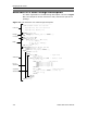
Language Structure Structure of a VHDL Design Description The basic organization of a VHDL design description is shown in Figure 2-1. The sample file shown includes an entity-architecture pair and a package. Figure 2-1: The Structure of a VHDL Design Description Comments Package -----------------------------------------PREP Benchmark Circuit #1: Data Path --- Copyright 1993, Data I/O Corporation. --- Copyright 1993, Metamor, Inc.
Language Structure Library Units Library units (also known as design units) are the main components of a VHDL description. They consist of the following kinds of declarations: • Package (optional) • Entity • Architecture • Configuration (optional) A design may include any number of package, entity, architecture, and configuration declarations. The relationship of the four types of design units is illustrated in Figure 2-2.
Language Structure Entity Entities contain the input and output definitions of the design. In VHDL designs that contain a hierarchy of lower-level circuits, the entity functions very much like a block symbol on a schematic. An entity usually has one or more ports, which are analogous to the pins on a schematic symbol. All information must flow into and out of the entity through the ports, as shown: library my_lib; use my_lib.example_arithmetic.
Language Structure Architecture The architecture is the actual description of the design. If you think of an entity as a functional block symbol on a schematic, then an architecture describes what's inside the block. An architecture can contain both concurrent and sequential statements, which are described below. Note that VHDL allows you to have more than one architecture for the same entity. For example, you might have an architecture for synthesis and a gate-level (netlist) architecture.
Language Structure Statements There are three basic kinds of statements in VHDL: • Declaration Statements • Concurrent Statements • Sequential Statements Declaration Statements Declaration statements are used to define constants (such as literal numbers or strings), types (such as records and arrays), objects (such as signals, variables and components), and subprograms (such as functions and procedures) that will be used in the design.
Language Structure Concurrent statements include the following: • Signal assignments (selected and conditional) • Component instantiations • Generate statements • Process statements • Procedure and function calls The following syntax shows an example of an architecture declaration with concurrent statements. Note that this code fragment also demonstrates how to include comments in VHDL source code.
Language Structure architecture behavior of some_thing is begin process begin wait until clock; if (accelerator = '1') then case speed is when stop => speed <= slow; when slow => speed <= medium; when medium => speed <= fast; when fast => speed <= fast; end case; end if; end process; end behavior; Note: Sequential statements do not imply, and are not the same as, sequential logic. Data Objects Data objects hold values.
Language Structure In these assignments, the variable named first_var is being assigned an integer value of 45 (For more information on data types, including integer, see the next section). A variable named SECOND_VAR is then assigned to whatever value first_var currently contains, which is 45. SECOND_VAR is then assigned the integer value 0. The variables named second_var and SECOND_VAR are the same, since VHDL is not case-sensitive.
Language Structure Like initial values, delays specified using the optional after keyword are ignored by the synthesis compiler, since it has no way of guaranteeing that a particular delay will occur in the target hardware. Therefore, you will not normally use the after clause when writing code for synthesis. However, it is important to realize that even without an after clause, all signal assignments occur with some infinitesimal delay, known as delta delay.
Language Structure Data Types VHDL supports a variety of data types. The type of a variable, signal, or constant determines the operators that are predefined for that object as well as the range of values that it can take on.
Language Structure Numeric Types The numeric types consist of integer, floating point (real), and physical types. Two encoding schemes are used by the VHDL Synthesizer for numeric types: • Numeric types and subtypes that contain a negative number in their range definition are encoded as two's complement numbers. • Numeric types and subtypes that contain only positive numbers are encoded as binary numbers.
Language Structure The encoding of integers in a binary format means that all ranges are rounded up to the nearest power of two. This means that if shorter had been declared as: subtype shorter is short range 0 to 16; then the result would have been the same after synthesis. Objects declared type of type integer without a range constraint will be synthesized into 32 wires. The are two predefined subtypes of integer.
Language Structure The Std_ulogic and Std_logic Data Types Std_ulogic (which is the base type of the more-commonly used resolved type std_logic) is a data type defined by IEEE standard 1164, and defined in the file ieee.vhd. Std_ulogic is an enumerated type, and has the following definition (from ieee.
Language Structure process(clk) begin if clk and clk'event then p <= p + 1; end if; end process; end behavior; In this example, type integer was used because the "+" operator is defined for integers but not for bit_vectors. The most common user-defined types are enumerated types, described in the previous section.
Language Structure if clk = '1' and clk'event then p <= To_Vector(2,To_Integer(p) + 1); end if; end process; end behavior; The example shown makes use of the package std_logic_ops in the dataio library provided with the VHDL synthesizer. This library includes commonly-used type conversion functions (such as To_Integer and To_Vector).
Language Structure Arithmetic Operators Arithmetic operators are used to create arithmetic functions. VHDL provides the following arithmetic operators: + * / mod rem abs ** Addition Subtraction Multiplication Division Modulus Remainder Absolute Value Exponentiation These operators are defined for numeric types such as integer and real. Note: Using arithmetic operators in a design can result in very large amounts of combinational logic being generated.
Language Structure When used with an array, the 'high attribute has a value of the highest array index: type my_array is array (0 to 99) of Boolean; variable info : my_array; info'high -- has a value of 99 There is a set of attributes that gives access to information about signal waveforms. Most of these signal attributes are for simulation, and have no other meaning. There is one signal attribute, however, that is often used to describe clock logic.
3. How to Write Synthesizable VHDL The hardware implementation of a design written in VHDL depends on many factors. Coding conventions, fitter technology, and optimization options are all factors. The general nature of a design also has a large impact on its suitability for synthesis to a particular device, independent of the method used to describe the design. Not all designs can be synthesized. Many VHDL designs (which are often referred to as models for simulation) are not suitable for synthesis.
How to Write Synthesizable VHDL In addition, a VHDL design written for simulation may use enumerated types to represent the encoding of a group of wires, perhaps as part of a symbolic state machine description. A design may also use enumerated types to represent the electrical characteristics on a signal wire (such as high impedance, resistive, or strong). In this case, the VHDL synthesizer has no way to distinguish the meaning (in terms of how the values should be represented in hardware) of each circuit.
How to Write Synthesizable VHDL Constants and Types The context in which an operator is used effects the generated circuitry. Using constant values or simple one-bit data types results in the most compact circuitry, while complex data types (such as arrays) in an expression result in correspondingly more circuitry. If one operand of a combinational expression is a constant, then less logic is generated.
How to Write Synthesizable VHDL m <= (a and b) or e; --concurrent signal assignments e <= c xor d; end example; Example 2: entity logical_ops_2 is port (a, b: in bit_vector (0 to 3); m: out bit_vector (0 to 3)); end logical_ops_2; architecture example of logical_ops_2 is begin m <= a and b; end example; Figure 3-1 shows how these examples are implemented in logic. In the first example, notice that the logic is shown in a multilevel implementation.
How to Write Synthesizable VHDL Relational Operators VHDL provides relational operators as shown in Table 3-1. Table 3-1: Relational Operators Operator Description = Equal /= Not equal to > Greater than < Less than >= Greater than or equal to <= Less than or equal to The equality operators ( = and /= ) are defined for all VHDL data types. The magnitude operators ( >=, <=, >, < ) are defined for numeric types, enumerated types, and some arrays.
How to Write Synthesizable VHDL Arithmetic Operators The arithmetic operators in VHDL are defined for numeric types (integer and real). The operators are listed in Table 3-2. In addition, overloaded versions of the + and - operators are supplied in the packages bit_ops and std_logic_ops for the types bit_vector and std_logic_vector, respectively. Note: The VHDL synthesizer does not distinguish between integer and real number values.
How to Write Synthesizable VHDL The absolute (abs) operator is not expensive to implement. The ** operator is only supported when its arguments are constants. The following example illustrates the logic generated for an addition operation: package example_arithmetic is type small_int is range 0 to 7; end example_arithmetic; use work.example_arithmetic.
How to Write Synthesizable VHDL Shift Operators The shift operators in VHDL are defined for the types bit and boolean. In addition, the package std_logic_ops found in the file \synario\lib5\dataio.vhd supplies overloaded operators for type std_logic_vector. The left-hand argument of these operators must be an array type (such as bit_vector or std_logic_vector) and the righthand argument must be an integer. The return value is always of the same type as the left-hand argument.
How to Write Synthesizable VHDL Concurrent Statement: Conditional Signal Assignment The following is an example of a conditional signal assignment: entity control_stmts is port (a, b, c: in Boolean; end control_stmts; m: out Boolean); architecture example of control_stmts is begin m <= b when a else c; end example; Note: In IEEE standard 1076-1993, the else clause is optional.
How to Write Synthesizable VHDL end process; end example; Case Statement Like the with statement, VHDL requires that all the possible conditions be represented in the condition of a case statement. To ensure this, use the others clause at the end of a case statement to cover any unspecified conditions. Note: Since std_ulogic and std_logic types have nine possible values (instead of two possible values for bit types), you should always include an others clause when using these types.
How to Write Synthesizable VHDL Describing Replicated Logic VHDL provides the following subprograms and looping constructs for creating replicated logic: • Function • Procedure • Loop Statement • Generate Statement Functions and procedures are collectively referred to as subprograms. Generate is a concurrent loop statement. These constructs are synthesized to produce logic that is replicated once for each subprogram call, or once for each iteration of a loop.
How to Write Synthesizable VHDL A procedure differs from a function in that there is no return value, and the arguments of the procedure have modes (in, out, or inout): entity proc is port (a: in bit_vector (0 to 2); m: out bit_vector (0 to 2)); end proc; architecture example of subprograms is procedure simple (w, x, y: in bit; z: out bit) is begin z <= (w and x) or y; end; begin process (a) begin simple(a(0), a(1), a(2), m(0)); simple(a(2), a(0), a(1), m(1)); simple(a(1), a(2), a(0), m(2)); end process; e
How to Write Synthesizable VHDL While statements are also supported by the VHDL synthesizer, with the constraint that the loop termination depend only on a value that can be determined at the time of synthesis (for example, a metalogic value. See Appendix B, “Limitations,” for more information about metalogic values).
How to Write Synthesizable VHDL Figure 3-5: Loop and Subprogram Statements Gen2: if test_flag = 1 generate test_pins <= current_state; end generate Gen2; When an if generation statement is used, the conditional expression (in this case "test_flag = 1") must be a metalogic value (one that does not depend on a signal or variable.
How to Write Synthesizable VHDL Describing Sequential Logic This section describes in detail how various kinds of registered sequential circuits can be described using VHDL, and how these descriptions are synthesized into actual circuitry (using latches and flip-flops). Describing sequential logic in VHDL is very much like programming in a conventional programming language, and less like programming using a traditional PLD programming language.
How to Write Synthesizable VHDL process(clk) begin if clk='1' then y <= a; else y <= b; end if; end process; Note: This example would result in an error during synthesis; because the conditional logic is completely specified using an else statement, the process describes a combinational function. The signals a and b are both inputs to the combinational function, and are therefore required to be in the sensitivity list.
How to Write Synthesizable VHDL Alternatively, you can describe a latch as transparent low by inverting the conditional logic: process(clk) begin if clk='1' then -- hold else y <= a; end if; end process; Or more concisely: process(clk) begin if clk='0' then y <= a; end if; end process; A rising edge flip-flop is created by making the clock input edge sensitive: process(clk) begin if clk'event and clk='1' then y <= a; end if; end process; If you are using the IEEE 1164 std_logic (or std_ulogic) data type
How to Write Synthesizable VHDL process(clk) begin if rising_edge(clk) then y <= a; end if; end process; In all these cases, the number of registers or the width of the mux are determined by the type of the signal y. Wait Statement The second method uses a wait statement within the process: process wait until expression; . . . end process; This statement suspends evaluation (over time) until an event occurs, and the expression evaluates to true.
How to Write Synthesizable VHDL Latches The following three examples each describe a level sensitive latch with an and function connected to its input. In all three of these examples the signal y retains its current value unless the clock input (clk) is high. Example 1: This example uses a process statement and conditional (if) statement.
How to Write Synthesizable VHDL Example 1: A process statement for a flip-flop is identical to the first latch example, above, with addition of the 'event attribute to specify an edge.
How to Write Synthesizable VHDL Note: In examples 1, 3 and 4, above, the clk and clk'event condition expression can be replaced with the IEEE 1164 rising_edge() function, if std_logic (or std_ulogic) is used for the Clk signal. Using rising_edge() can improve the accuracy of simulations, particularly in cases where you are simulating transitions from uninitialized states.
How to Write Synthesizable VHDL Synchronous Set/Reset To add the behavior of synchronous set or reset you can simply add a conditional assignment to a constant value immediately inside the clock specification. This is a VHDL coding convention that is recognized as a hardware reset by the VHDL synthesizer. Other methods of reset control may have the desired behavior, but do not result in a hardware reset feature being utilized.
How to Write Synthesizable VHDL elsif clk='1' and clk'event then y <= a and b; end if; end process; Devices with both an asynchronous reset and preset are also supported, as long as the reset overrides the preset condition.
How to Write Synthesizable VHDL You can combine the asynchronous reset and preset to create an asynchronous load: library ieee; use ieee.std_logic_1164.all; library dataio; use dataio.std_logic_ops.
How to Write Synthesizable VHDL Template State Machine The recommended method for describing synthesizable state machines in VHDL is to use an enumerated type to define the states of the machine, and use two processes to clearly distinguish between the registered portion of the machine (the state registers and registered state machine outputs) and the combinational portion (the state transition logic and combinational state machine outputs).
How to Write Synthesizable VHDL This state machine description includes two combinational outputs (port comb_outputs) that decode the current state of the machine. If these outputs were registered, rather than combinational, then a third process would have been written for the outputs, using the clk and reset inputs in the process sensitivity list.
How to Write Synthesizable VHDL architecture example of some_entity is begin process (clk) begin if clk = '1' and clk'event then if reset = '1' then c <= '0'; else c <= a and c; -- c is fed back directly end if; end if; end process; end example; This method eliminates the intermediate signal b. Feedback on Variables Variables exist within a process, and preserve their data as processes suspend and reactivate.
How to Write Synthesizable VHDL Types of State Machines Classical state machines can be classified as Moore or Mealy machines. In a Moore machine, the output is a function of the current state only, and can change only on a clock edge. Mealy machines, on the other hand, have outputs that are a function of the current state and the current inputs. The outputs of a Mealy machine may change when any input changes.
How to Write Synthesizable VHDL A more compact description of this architecture could be written as follows: architecture moore2 of system is signal C: std_logic; begin Combinational: process (C) -- combinational -logic begin D <= F2(C); end process; Registers: process (clock) -- sequential logic begin if rising_edge(clock) then C <= F1(A, C); end if; end process; end moore2; Output Registers If the system timing requires that there be no logic between the registers and the output (the shortest output prop
How to Write Synthesizable VHDL Input Registers If the system timing requires no logic between the registers and the input (a short setup time is required) the following architecture can be used: architecture moore4 of system is signal A1, D1 : std_logic; begin Registers: process (clock) begin if rising_edge(clock) then A1 <= A; D1 <= D; end if; end process; F1: process (A1, D1) begin D <= F(A1,D1); end process; end moore4; The resulting circuitry is diagrammed in Figure 3-8.
How to Write Synthesizable VHDL Mealy state machines can be written more clearly, however, if three processes are used in the following style: architecture mealy of system is signal C: std_logic; signal B: std_logic; begin Registers: process (clock) -- State register begin if rising_edge(clock) then C <= B; end if; end process; Transitions: process (A, C) -- Transition logic begin B <= F1(A, C); end process; Outputs: process (A,C) -- Mealy outputs begin D <= F2(A, C); end process; end mealy; Figure 3-9 sho
How to Write Synthesizable VHDL Perhaps the most common mistake made by new VHDL users (particularly those who have had experience with PLD-oriented languages) is in assuming that unspecified conditions will have no effect on the logic of the generated circuit. This is not the case in VHDL, and you need to be aware of the logic that will be generated for incompletely specified conditions.
4. How to Control the Implementation of VHDL Using Enumerated Types Enumerated types are very important in VHDL, and are the only way in which signals that require more than two values (such as those with output enables) can be described in the language. For many circuits, most notably state machines, enumerated types can help to make complex designs more readable, and can also help to increase the efficiency of the resulting synthesized circuitry.
How to Control the Implementation of VHDL The type std_ulogic (from which std_logic is derived) is also an enumerated type, and has the definition (from ieee.vhd): type std_ulogic is ( 'U', 'X', '0', '1', 'Z', 'W', 'L', 'H', '-' ); ---------- Uninitialized Forcing Unknown Forcing 0 Forcing 1 High Impedance Weak Unknown Weak 0 Weak 1 Don't care The std_ulogic (or std_logic) data type is very important for both simulation and synthesis.
How to Control the Implementation of VHDL An example of a state machine design that uses enum_encoding to specify a particular (non-sequential) encoding of state values is presented in the tutorials chapter of the VHDL Entry manual. The prep4 (complex state machine) example presented in that chapter uses enum_encoding to specify an encoding that is optimized for a complex PLD implementation, as well as using explicit assignments to the ’-’ value to include don’t-care information about the circuit’s outputs.
How to Control the Implementation of VHDL Of these four possible values, only the 1 and 0 result in logic being generated for a signal, so an element of an enumerated type that is defined using any of the four characters results in only a single wire being generated. For enumerated type elements that are defined using the “-” character, the VHDL synthesizer generates a don’t-care for the signal. This often results in better logic optimization.
How to Control the Implementation of VHDL type cpu_op is (execute, load, store); Two wires with the values 00, 01, and 10; the binary encoding 11 is a don’tcare. subtype mem_op is cpu_op range load to store; Two wires with the values 01 and 10; the encodings 00 and 11 are don’tcares.
How to Control the Implementation of VHDL Controlling Output Inversion Many common PLDs feature inverted registered outputs, or outputs that have programmable inverters between the outputs of the flip-flops and the actual output pins. When designing for these devices, precise control over the polarity of the outputs is often required. Using properties of the VHDL synthesizer, you have three options available for controlling output polarities.
How to Control the Implementation of VHDL o1,o2: out std_logic); end polarity; architecture inversion of polarity is signal n2: std_logic; begin process(clock) begin if rising_edge(clock) then o1 <= (a and b); n2 <= (not a or not b); end if; end process; o2 <= not n2; end inversion; VHDL Reference Manual 4-7
How to Control the Implementation of VHDL Controlling Feedback Paths If the design description specifies feedback, then the VHDL synthesizer will generate the feedback logic according to how the fed back signal was used in the design. There are two basic types of feedback generated from the VHDL synthesizer: macrocell (register) feedback and pin feedback. The source of the feedback (register or pin) may be controlled by using appropriate VHDL coding conventions.
How to Control the Implementation of VHDL entity counter1 is port (clock: in Boolean; count: inout integer range 0 to 7; end counter1; architecture pin_feedback of counter1 is begin process (clock) begin if clock and clock'event then if count = 7 then count <= 0; else count <= count + 1; end if; end if; end process; end pin_feedback; Note: Mode inout should only be used to describe true directional ports—those that have an output enable function associated with them.
How to Control the Implementation of VHDL Selecting a Base Data Type An important consideration when starting a VHDL design project is the data type upon which your design is to be based. Typically, you will use one of the following types: • Integer • Bit and bit_vector • Std_ulogic and std_ulogic_vector • Std_logic and std_logic_vector • Std_logic and the unsigned/signed data types defined by IEEE 1076.
How to Control the Implementation of VHDL The problem with this code is that whenever the sum of a and b exceeds 7, a fatal error will occur during simulation.
How to Control the Implementation of VHDL Using IEEE 1076.3 Unsigned/Signed Types In late 1995 the IEEE 1076.3 commitee approved a new VHDL package called numeric_std. This package defines two vector types, unsigned and signed, and the appropriate overloaded operators for these types. Both unsigned and signed are based upon the std_logic type. This has several implications: • You can not assign a signal of type std_logic_vector to one of type unsigned (or signed) or visa-versa.
How to Control the Implementation of VHDL Synthesis of Don't Cares If you are designing using the type std_logic as your base type (as recommended in the previous section) you are probably aware that one of the values in the enumeration of std_logic is '-', which is commented in the std_logic_1164 package as meaning "don't care". Unfortunatly, none of the functions defined by 1164 actually give '-' such a meaning. For example, the following expression: if ('1' = '-') then ...
How to Control the Implementation of VHDL Pinnum Attribute You can specify pin and node numbers in the VHDL source file using the custom attribute pinnum. special attribute is recognized by the VHDL synthesizer and is written to the output for use by device fitting software. This attribute has no other meaning to the VHDL synthesizer, or to any other VHDL software (such as a simulator). The information is simply passed on to the device fitting software. To use the pinnum attribute: 1.
How to Control the Implementation of VHDL To specify node numbers: 1. Declare the signal in the entity (not the architecture). 2. If the signal is combinational, associate a critical attribute with it, as in the following example: library metamor; use metamor.attributes.
How to Control the Implementation of VHDL If you will be assigning properties to signals that are part of nonbinary data types (such as bit_vector, integer or std_logic_vector), then you will need to be aware of how the VHDL synthesizer generates signal names from these data types. When the VHDL synthesizer expands an array data type into signals for each bit, it appends a numeric suffix to the array name in the format _n_, where n is the array index for each element of the data type.
How to Control the Implementation of VHDL or2: out std_logic); end component; attribute macrocell: boolean; attribute macrocell of submod_def: component is true; begin myblock: submod_def port map(in1=>a, in2=>b, and1=>out1, or2=>out2); end schematic; In this example, the hierarchical reference to the submod_def design unit will result in a reference being generated for an external module named submod_def. The VHDL synthesizer will not attempt to find or synthesize the submod_def design unit.
How to Control the Implementation of VHDL Enum_encoding Attribute The enum_encoding attribute allows you to override the default encoding of VHDL enumerated types. This is most useful when you want to specify a non-sequential encoding for an enumerated type. For example, you might want to use enum_encoding to specify the exact encoding of each state in a state machine.
5. VHDL Datapath Synthesis A common problem with using VHDL synthesis for FPGA and PLD design is that synthesis tools often to a relatively poor job of implementing datapath logic (wide adders, counters, multipliers, and the like). There are a number of potential reasons for this: • Datapath functions such as adders have many different potential implementations, all representing different speed/density tradeoffs.
VHDL Datapath Synthesis How Inferencing Works Inferencing is currently supported for the following macros: ♦ ADD_SUB ♦ MULT ♦ COUNTER ♦ COMPARE Inferencing is performed based upon a combination of the operators (+, -, >, etc.) that appear in your VHDL code and the context in which those operators appear. For example, signal a, b, c: std_logic_vector(7 downto 0); c <= a + b; would infer an ADD_SUB configured to perform addition.
VHDL Datapath Synthesis To View the Results of Inferencing: 1. Select the Synthesize Logic process, and click on the Properties button. 2. Set the property Show Inferred Structure to True. 3. Run the Synthesize Logic process for the module. 4. Click the Log button. The Synario Report Viewer opens on the log file. See Figure 5-1 for an example of the inferencing portion of a log file.
VHDL Datapath Synthesis If this happens because of an inferred macrofunction, turn LPM inferencing off. If it happens because of an instantiated macrofunction, either replace that macrofunction, or consider using it in a different manner. For example, in this case using a synchronous reset will map to an Orca device. In all cases be sure to consult the Device Kit manual for your target device, it will contain details on any limitations that apply to that device.
VHDL Datapath Synthesis COUNTER Inference of the COUNTER macro works very similarly to that for the ADD_SUB.
VHDL Datapath Synthesis COMPARE The COMPARE macrofunction will be inferred from the use of any of the following relational operators: <, <, >=, <=, =, /=. A COMPARE will only be inferred when both of the operands are not constant values.
VHDL Datapath Synthesis Inferencing Details This section provides additional details on inferencing. Supported Types Inferencing is supported for operands of type bit_vector, std_logic_vector, IEEE unsigned, and integer. If you are synthesizing designs originally developed in the Synopsys environment, the type unsigned in the package stdarith.std_logic_arith may also be used. In general, integer is a poor choice.
VHDL Datapath Synthesis Resource Sharing Consider the following simple ALU: p0: process(operand0, operand1, begin case(opcode) when ADD_OPERAND1 => result <= operand0 when SUB_OPERAND1 => result <= operand0 when ADD_OPERAND2 => result <= operand0 when others => result <= operand0 end case; end process; operand2, opcode) + operand1; - operand1; + operand2; - operand2; Because resource sharing is not currently supported, this code will infer 4 different ADD_SUB macros.
VHDL Datapath Synthesis Instantiation Details If you are planning to do direct instantiation of the Synario Generic Datapth macrofunctions, you will need to add the following library/use statements to your source code: library gen_dp; use gen_dp.components.all; The source code for this package can be found in \lib5\gen_dp.vhd, where refers to your Synario installation directory.
VHDL Datapath Synthesis i_addsub0: g_add_sub generic map (width => 8, representation => "UNSIGNED") port map(dataa=>din0, datab=>din1, sum=>add_sub_out); Note that the REPRESENTATION generic must be assigned a valid value, even though it is defined to have default value in the component declaration. This is true for all datapath macrofunctions.
VHDL Datapath Synthesis to up counter. Aset Optional Logic 0 Asynchronous set input Sets all Q outputs high Aclr Optional Logic 0 Asynchronous clear input Sets all Q outputs low Aconst Optional Logic 0 Asynchronous set/clear input Sets the Q output to the value of the AVALUE generic. If used, neither the Aset or Aclr inputs can be used. Aload Optional Logic 0 Asynchronous load input Sets the Q output to the value of the Data input.
VHDL Datapath Synthesis G_COUNTER also has the following generics: Generic Usage Description Comments Width Required The width, in bits, of the Dataa, Datab, and Sum ports. Must be an integer value >= 2. Representation Required Indicates whether UNSIGNED or SIGNED math is to be performed. Only the value UNSIGNED is currently supported. Modulus Optional The terminal count of the counter. If not set, terminal count will default to 2**WIDTH - 1.
VHDL Datapath Synthesis G_MULT The following table describes the ports of the G_MULT: Port Usage Default Value Description Comments Dataa Required None First data input Size equals WIDTHA generic. Datab Required None Second data input Size equals WIDTHB generic. Sum Optional Logic 0 Partial Sum. Size equals WIDTHS generic. Product Optional None Product output. Product = Dataa * Datab + Sum. Size equals WIDTHP generic. Notes: 1. Most targets do not support the Sum port.
VHDL Datapath Synthesis G_ROM At the current time G_ROM is never inferred. It may be instantiated, but is only supported for Altera targets, where it maps directly to the Altera LPM_ROM macro. See the Altera MaxPlus documentation for details. Functional Simulation Functional simulation models for the Synario generic datapath macrofunctions are supplied in the file \generic\vhdl\gen_dpe.vhd.
6. How to Manage VHDL Design Hierarchies Managing Large Designs This section shows you how to use partitioning and design management to manage larger designs. The VHDL constructs for partitioning and sharing code modules are the component, configuration, block and library statements. You should refer to a standard VHDL reference text for detailed descriptions of these partitioning statements. In this section, methods for design partitioning that are most relevant to synthesis will be discussed.
How to Manage VHDL Design Hierarchies Components VHDL design entities can be referenced from other architectures as components. VHDL allows you to manage the mapping of design entities to components with a configuration specification (described in the next section) that associates particular component instances with a specified design entity.
How to Manage VHDL Design Hierarchies In this example, the architecture of addmult contains a declaration of two components, add and mult, and one instance of each component. The three design entities are arranged in the hierarchy shown in Figure 6-1. Figure 6-1: Hierarchy of the Addmult Multiplexer Hierarchical designs contain multiple design entities, and may be written using more than one source file, or by entering multiple design entities (entity/architecture pairs) in the same source file.
How to Manage VHDL Design Hierarchies When you simulate a design consisting of multiple VHDL files, you must compile the design from the bottom up, beginning with the VHDL files containing the lowest-level design entities (those that contain no references to other VHDL design units). The VHDL simulator does not allow VHDL source files to be compiled if they contain references to lower-level design entities that have not yet been compiled.
How to Manage VHDL Design Hierarchies Configurations can also be used to re-map the ports of a component and its lower-level entity, making it possible to substitute lower-level entities that do not directly correspond to the component instance being described at the higher-level.
How to Manage VHDL Design Hierarchies ... end design_io; Placing a use clause before an entity causes the contents of the specified package contents to be visible to that entity and its architecture(s), but nowhere else. This means that you must include a use statement before each entity/architecture pair in the design that requires access to package contents.
How to Manage VHDL Design Hierarchies Using Packages For Common Declarations To define common declarations (such as types, subtypes or subprograms), you may want to use a package that is shared between different VHDL sources files.
How to Manage VHDL Design Hierarchies Using Design Libraries In most VHDL simulation environments, design libraries are areas in which pre-compiled (analyzed) design units are stored. An good example of such a library is the IEEE library, which is pre-compiled into a library accessible to the VHDL simulator. The form that the precompiled library takes is dependent upon the simulator being used, and compiled libraries are generally not compatible between different simulator programs.
How to Manage VHDL Design Hierarchies Work is the default name of the current library. The work library is where, in a simulation system, all of your design units (entities, architectures, packages, and configurations) will be placed after they are analyzed, unless you have specified an alternate (named) library. Unlike simulation environments, the VHDL synthesizer only considers design units that are currently being compiled (those in the current source file) to be in the work library.
How to Manage VHDL Design Hierarchies • The names that you use in your schematic for net or instance names must be valid VHDL identifiers. Refer to the rules for VHDL identifier names, and check the list of VHDL keywords provided in Appendix A if you are unsure if a particular name is a valid VHDL identifier. Avoid using underscore (’_’) characters at the beginning or end of names, as this is not allowed in VHDL names.
How to Manage VHDL Design Hierarchies The generics library is also provided in source file form in the generic\vhdl subdirectory, but this file (generics.vhd) is not used during processing for simulation or for synthesis. It is only provided for your information. An example of how to map the generics library during simulation can be found in the tutorials chapter in the VHDL Entry manual, in the final tutorial example (prep2).
How to Manage VHDL Design Hierarchies 6-12 VHDL Reference Manual
A. VHDL Quick Reference This appendix contains basic reference information for VHDL syntax. For complete information, refer to the IEEE Standard 1076-1993 VHDL Language Reference Manual or to a standard VHDL text.
VHDL Quick Reference VHDL Syntax Basics The following code fragments illustrate the syntax of VHDL statements: Declarations -- OBJECTS constant alpha : character := 'a'; variable total : integer ; variable sum : integer := 0; signal data_bus : bit_vector (0 to 7); -- TYPES type type type type opcodes is (load,store,execute,crash); small_int is range 0 to 100; big_bus is array ( 0 to 31 ) of bit; glob is record first : integer; second : big_bus; other_one : character; end record; -- SUBTYPES subtype subty
VHDL Quick Reference Sequential Statements --IF STATEMENT if increment and not decrement then count := count +1; elsif not increment and decrement then count := count -1; elsif increment and decrement then count := 0; else count := count; end if; --CASE STATEMENT case day is when Saturday to Sunday => work := false; work_out := false; when Monday | Wednesday | Friday => work := true; work_out := true; when others => work := true; work_out := false; end case; -- LOOP,NEXT,EXIT STATEMENTS L1 : for i in 0 to
VHDL Quick Reference Subprograms -- FUNCTION DECLARATION -- parameters are mode in -- return statements must return a value function is_zero (n : integer) return Boolean is -- type, variable,constant,subprogram declarations begin -- sequential statements if n = 0 then return true; else return false; end if; end; -- PROCEDURE DECLARATION -- parameters may have mode in , out or inout procedure count (incr : Boolean; big : out bit; num : inout integer) is -- type, variable,constant,subprogram declarations beg
VHDL Quick Reference Concurrent Statements -- BLOCK STATEMENT label5 : -- label is required block -- type, signal,constant,subprogram declarations begin -- concurrent statements end block; -- PROCESS STATEMENT , sequential first form label3 : -- label is optional process -- type, variable,constant,subprogram declarations begin wait until clock1; -- sequential statements end process; -- PROCESS STATEMENT , sequential second form process ( en1, en2, clk) -- ALL signals used in -- process -- type, variable,co
VHDL Quick Reference -- GENERATE STATEMENT label4 : -- label required for i in 0 to 9 generate -- concurrent statements if i /= 0 generate -- concurrent statements sig(i) <= sig(i-1); end generate; end generate; ---U1 -U2 COMPONENT INSTANTIATION label is required positional association : decode port map (instr, rd, wr); named association : decode port map (r=> rd, op => instr, w=> wr); -- CONDITIONAL SIGNAL ASSIGNMENT total <= x + y; sum <= total + 1 when increment else total -1; -- SELECTED SIGNAL ASSIGN
VHDL Quick Reference Library Units -- PACKAGE DECLARATION package globals is -- type,constant, signal ,subprogram declarations end globals; -- PACKAGE BODY DECLARATION package body globals is -- subprogram definitions end globals; -- ENTITY DECLARATION entity decoder is port (op : opcodes; r,w : out bit); end decoder; -- ARCHITECTURE DECLARATION architecture first_cut of decoder is -- type, signal,constant,subprogram declarations begin -- concurrent statements end first_cut; -- CONFIGURATION DECLARATION co
VHDL Quick Reference Attributes ♦ ATTRIBUTES DEFINED FOR TYPES T'base the base type of T T'left left bound of T T'right right bound of T T'high high bound of T T'low low bound of T T'pos(N) position number of N in T T'val(N) value in T of position N T'succ(N) T'val(T'pos(N) +1) T'pred(N) T'val(T'pos(n) -1) T'leftof(N) T'pred(N) if T is ascending T'succ(N) if T is descending T'rightof(N) T'succ(N) if T is ascending T'pred(N) if T id descending T'image(N) string representing value of N T'value(N) value of s
B. Limitations VHDL is a technology-independent language and has a very large feature set. Because the VHDL software is specifically targeted toward logic design, some VHDL constructs are not applicable to synthesis. Constraints and Unsupported Constructs This section lists the VHDL constructs that are not supported by the VHDL synthesizer, or whose use is constrained. Unsupported Constructs The following constructs are not supported; using them results in a constraint error.
Limitations • A process sensitivity list must contain all signals that the process is sensitive to. Constrained Expressions Certain expressions metalogic expressions which simply means they evaluate to a constant value, and are not dependent on a signal (they do not change over time). • Operands of ** must be metalogic expressions. • Assignments to elements of an array must have an index that is a metalogic expression.
C. VHDL for the ABEL-HDL Designer This Appendix compares ABEL-HDL and VHDL design strategies and is intended for the experienced ABEL-HDL designer who has little or no experience with VHDL.
VHDL for the ABEL-HDL Designer port (pin_list: [mode] type [; pin_list: [mode] type ...]); The mode of a port in VHDL describes its dataflow direction. A port's mode can be in, out, buffer, or inout. The default mode is in. (It is good VHDL coding practice to include in for all input ports.) There is no equivalent in ABEL-HDL to mode. Pin declarations in ABEL-HDL do not indicate whether signals are inputs, outputs, or bidirectional.
VHDL for the ABEL-HDL Designer Figure C-1: Block Diagram for cntbuf Design In this example, the port statement defines the data types. (This example uses the IEEE 1164 std_logic data types. These data types are described in detail in Chapter Error! Reference source not found., “Error! Reference source not found..”) The VHDL pinnum attribute statement is then used to assign actual pin numbers to the design's I/O ports: library ieee; use ieee.std_logic_1164.
VHDL for the ABEL-HDL Designer s1,s0 c0,c1 equations c0 = b0 s0 = b0 c1 = b1 s1 = b1 end pin istype 'com'; "sum pin istype 'com'; "carry bits & $ $ $ a0; a0; a1; a1 $ c0; " " " " carry from bit 0 sum of bit 0 carry out sum for bit 1 Describing Combinational Logic in VHDL In VHDL, you can describe combinational logic using concurrent statements in the architecture section of your program.
VHDL for the ABEL-HDL Designer To describe a registered function in structural or dataflow VHDL, you can add a procedure to define the memory elements.
VHDL for the ABEL-HDL Designer architecture adder_ff of add is signal f,g: bit; procedure dff(signal clk,d: bit; signal q: out bit) is begin if clk and clk'event then q <= d; end if; end; procedure add(signal a0,a1,b0,b1: bit; signal c0,c1 out bit) is variable x,y : bit begin c0 <= b0 and a0; -- carry from bit 0 s0 <= b0 xor a0; -- sum for bit 0 c1 <= b1 xor a1; -- carry out s1 <= b1 xor a1 xor c0; -- sum for bit 1 end; begin add(a0,a1,b0,b1,f,g); dff(clk,f,c0); dff(clk,g,c1); end adder_ff; Since descripti
VHDL for the ABEL-HDL Designer or, using the IEEE 1164 std_logic data types (which are described in more detail in Chapter Error! Reference source not found., “Error! Reference source not found.” and in Chapter Error! Reference source not found., “Error! Reference source not found.
VHDL for the ABEL-HDL Designer Perhaps the most common mistake that is made by new VHDL users (who have had experience with PLD-oriented languages) is the assumption that unspecified conditions will have no effect on the logic of the generated circuit. Perhaps the most common example of this is in the use if conditional assignments within process statements.
VHDL for the ABEL-HDL Designer State Machines Describing State Machines in ABEL-HDL In ABEL-HDL, you describe a state machine similar to the way you create a behavioral model in VHDL. You create a state description for each possible state of the machine, beginning each with a description of the state value to be stored in the state registers. For example: module st_mach q1,q0 pin A,B pin istype 'reg'; istype 'com'; equations [q1,q0].
VHDL for the ABEL-HDL Designer library ieee; use ieee.std_logic_1164.
VHDL for the ABEL-HDL Designer A Standard ABEL-HDL Design in VHDL The VHDL source file, cntbuf.vhd, shows how one of the standard ABEL-HDL examples can be written in VHDL. This example demonstrates: • Pin assignments • Bidirectional I/O • Output enable conventions • Synchronous reset logic The complete VHDL description is listed below. ---------------------------------------------------------- VHDL Version of standard ABEL example CNTBUF.ABL -- Michael Holley, Data I/O Corp.
VHDL for the ABEL-HDL Designer end if; end process; process (Clk,OE,Count) -- Counter begin if rising_edge(Clk) then -- Edge triggered if Clr = '1' then Count <= 0; elsif Count = 15 then Count <= 0; else Count <= Count + 1; end if; end if; if OE = '1' then Q <= "ZZZZ"; -- Make Q high Z else Q <= To_Vector(4,Count); end if; end process; end example; Design I/O In this design, the I/O ports are assigned to pins as described earlier in this chapter.
VHDL for the ABEL-HDL Designer Because IEEE 1164 std_logic_vector data types do not have a '+' operator defined for them, the counter portion of the design has been described using an integer data type (the signal Count). A type conversion function (To_Vector) has been used to convert the integer data type into a std_logic_vector data type suitable for the design's output. This type conversion function (and others) is provided in the dataio library supplied with the VHDL option.
VHDL for the ABEL-HDL Designer C-14 VHDL Reference Manual
D. ABEL-HDL Language Reference The information in this appendix is provided to help you read and interpret the logic equations that the Project Navigator produces in reports and error messages. These equations use a subset of the ABELHDL equation language to represent the logic of your design. These equations are produced by most device fitter software, as well as the equation report generator, which displays the Synthesized, Reduced and Linked Equations.
How to Control the Implementation of VHDL Dot extensions Identifier names used in ABEL-HDL equations may include dot extensions. Dot extensions provide a means to refer specifically to internal signals and nodes that are associated with a primary signal in a design. Dot extensions are used in complex language constructs, such as nested sets or complex expressions. Pin-to-Pin Vs.
How to Control the Implementation of VHDL Dot Ext. Pin-topin Description .COM ü A combinational feedback from the flip-flop data input, normalized to the pin value and used to distinguish between pin (.PIN) and internal logic array (.COM) feedback. .D .FB When on the left side of an equation, .D is the data input to a D-type flip-flop; on the right side, .D is combinational feedback. ü Register feedback .FC Flip-flop mode control .J J input to a JK-type flip-flop .
How to Control the Implementation of VHDL Detailed Design Dot Extensions Table C-3 shows the dot extensions that are used to describe different register types. The required dot extensions are indicated with a check in the Extension Required column. Table C-3: Dot Extensions for Device-specific (detailed) Designs Register Type Extensi on Requir ed combinational (no register) D-4 Support ed Extensio ns Definition .oe .pin .com output enable pin feedback combinational feedback D-type flip-flop ü ü .
How to Control the Implementation of VHDL Register Type Extensio n Require d Supporte d Extensio ns Definition T-type flip-flop ü ü .clk .t .oe .q .sp .sr .ap .ar .pin clock toggle input output enable flip-flop feedback synchronous preset synchronous reset asynchronous preset asynchronous reset pin feedback L-type latch ü ü .d .le .lh .oe .q .
How to Control the Implementation of VHDL Figure C-1 through Figure C-9 show the effect of each dot extension. The actual source of the feedback may vary from that shown.
How to Control the Implementation of VHDL Figure C-4: Detailed Dot Extensions for an Inverted T-type Flip-flop Architecture Figure C-5: Detailed Dot Extension for an Inverted RS-type Flip-flop Architecture Figure C-6: Detailed Dot Extensions for an Inverted JK-type Flip-flop Architecture VHDL Reference Manual D-7
How to Control the Implementation of VHDL Figure C-7: Detailed Dot Extensions for an Inverted Latch with Active High Latch Enable Figure C-8: Detailed Dot Extensions for an Inverted Latch with Active Low Latch Enable D-8 VHDL Reference Manual
How to Control the Implementation of VHDL Figure C-9: Detailed Dot Extensions for an Inverted Gated-clock D Flip-flop VHDL Reference Manual D-9
How to Control the Implementation of VHDL D-10 VHDL Reference Manual
Index A abs..................................................................................................... 2-17, 3-6 Addition operators .........................................................................................3-7 and.......................................................................................................... 2-16 Architecture........................................................................................... 2-2, 2-5 Arithmetic operators ............................
Index Combinational logic ................................................................................3-2, C-3 Component statement ...................................................................................6-1 Components .................................................................................................6-2 synthesis advantages..................................................................................6-3 Concurrent statement....................................................
Index F Feedback ................................................................................................... 3-26 Feedback on signals .................................................................................... 3-26 Feedback on variables.................................................................................. 3-27 Feedback paths.............................................................................................4-8 Finite state machines......................................
Index Library statement................................................................................... 6-1, 6-6 Logic equations ABEL-HDL dot extensions ........................................................................... D-1 Logical operators.................................................................................. 2-16, 3-3 Loop .......................................................................................................... 3-11 Loop ranges......................................
Index or ............................................................................................................ 2-16 Others ................................................................................................ 3-9, 3-10 Out ......................................................................................................4-8, C-2 Output enable...................................................................................... 4-5, C-12 Output enable logic ..............................
Index lower-level .............................................................................................. 6-10 top-level ...................................................................................................6-9 using with VHDL.........................................................................................6-9 Selected signal assignment ..................................................................... 3-8, 3-9 Sensitivity .......................................................
Index T Textio package..............................................................................................2-1 Top-Level Entity property ....................................................................................................6-4 Type checking............................................................................................. 2-15 Types enumerated ...............................................................................................4-2 std_ulogic ......................
Index Index-8 VHDL Reference Manual