IBUS-BAT-I370 System Board Users Manual 37610914
Copyright This publication contains information that is protected by copyright. No part of it may be reproduced in any form or by any means or used to make any transformation/adaptation without the prior written permission from the copyright holders. This publication is provided for informational purposes only.
CE, FCC and DOC Statement This equipment has been tested and found to comply with the limits for a Class B FCC and Class A CE digital device. These limits are designed to provide reasonable protection against harmful interference when the equipment is operated in a residential installation. This equipment generates, uses and can radiate radio frequency energy and, if not installed and used in accordance with the instruction manual, may cause harmful interference to radio communications.
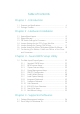
Table of Contents Chapter 1 - Introduction 1.1 Features and Specifications.................................................................................. 6 1.2 Package Checklist......................................................................................................... 11 Chapter 2 - Hardware Installation 2.1 2.2 2.3 2.4 2.5 2.6 2.7 System Board Layout ............................................................................................. System Memory................................
Appendix A - System Error Messages A.1 POST Beep....................................................................................................................... 60 A.2 Error Messages.............................................................................................................. 60 Appendix B - Troubleshooting B.1 Troubleshooting Checklist....................................................................................
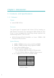
Introduction Chapter 1 - Introduction 1.1 Features and Specifications 1.1.1 Features Chipset Intel 440BX AGPset Processor The system board is equipped with Socket 370 for installing an Intel CeleronTM processor that is packaged in PPGA (Plastic Pin Grid Array). It is also equipped with a switching voltage regulator that automatically detects 1.30V to 2.05V.
Introduction Expansion Slots The system board is equipped with 1 dedicated AGP slot. AGP is an interface designed to support high performance 3D graphics cards. It utilizes a dedicated pipeline to access system memory for texturing, z-buffering and alpha blending; delivering up to 533MB/ sec. bandwidth for 3D graphics applications. AGP in this system board will deliver faster and better graphics with your PC.
Introduction PCI Bus Master IDE Controller Two PCI IDE interfaces support up to four IDE devices Supports ATA/33 or ATA/66 hard drives PIO Mode 3 and Mode 4 Enhanced IDE (data transfer rate up to 16.6MB/sec.) Bus mastering reduces CPU utilization during disk transfer Supports ATAPI CD-ROM, LS-120, ZIP and SCSI sequential bootup IrDA Interface The system board is equipped with an IrDA connector for wireless connectivity between your computer and peripheral devices.
Introduction 1.1.2 Intelligence Automatic CPU/Chassis Fan Off The CPU and chassis fans will automatically turn off once the system enters the Suspend mode. Dual Function Power Button (ATX power supply only) Depending on the setting in the BIOS setup, this switch will allow the system to enter the Soft-Off or Suspend mode.
Introduction Important: The power button will not function once a keyboard password has been set in the KB Power On Password field of the Integrated Peripherals setup. You must type the correct password to power-on the system. The 5VSB power source of your power supply must support ≥720mA (minimum). ACPI (ATX power supply only) The system board is designed to meet the ACPI (Advanced Configuration and Power Interface) specification.
Introduction 1.
Hardware Installation Chapter 2 - Hardware Installation 2.
Hardware Installation 2.2 System Memory The 168-pin DIMM (Dual Inline Memory Module) sockets support PC SDRAM DIMM, 3.3V. PC SDRAM (Synchronous Dynamic Random Access Memory) is a fast memory interface technology that includes using the clock on the chip to synchronize with the CPU clock so that the timing of the memory chips and the timing of the CPU are synchronized. This saves time during transmission of data, subsequently increasing system performance.
Hardware Installation 1. Pull the tabs which are at the ends of the socket to the side. 2. Position the DIMM above the socket with the notches in the module aligned with the keys on the socket. 3. Seat the module vertically into the socket. Make sure it is completely seated. The tabs will hold the DIMM in place. 2.3 DIP Switch Settings for Processors (For Factory Use Only) You cannot overclock an Intel CeleronTM PPGA processor because its frequency ratio has been fixed by the manufacturer.
Hardware Installation Processor Processor 66MHz 100MHz Frequency Ratio 4.5x 433MHz Future processor 6.5x Future processor 5x 466MHz Future processor 7x 366MHz Future processor 5.5x Future processor Future processor 7.5x 400MHz Future processor 6x Future processor Future processor 8x 66MHz 100MHz 300MHz Future processor 333MHz Frequency Ratio SW1 SW1 Note: Intel CeleronTM PPGA processors support VID (Voltage Identification).
Hardware Installation Jumper JP2s settings are shown below. 1 1 1 2 2 2 3 3 3 1-2 On: Auto (default) 2-3 On: 66MHz 1-2-3 Off: 100MHz 2.5 Jumper Settings for Clearing CMOS Data Jumper JP6 Clear CMOS Data If, for some reason, the CMOS data becomes corrupted or you forgot the supervisor/user/ keyboard password, the system can be reconfigured with the default values stored in the ROM BIOS. To load the default values, power off your system and unplug the power cord.
Hardware Installation 2.6 Jumper Settings for Wake-On-Keyboard/ Wake-On-Mouse (ATX power supply only) Jumper JP1 Wake-On-Keyboard/Wake-On-Mouse The system board supports the Wake-On-Keyboard/WakeOn-Mouse function. This function allows you to use the keyboard or mouse to poweron the system. By default, JP1 is disabled. To use this function, set JP1 to 2-3 On. Keyboard/ Mouse Power On in the Integrated Peripherals setup of the Award BIOS must be set accordingly. Refer to chapter 3 for details. Warning: 1.
Hardware Installation 2.7 Connecting the Ribbon Cables and Wires of the Ports and Connectors 2.7.1 Serial Ports The built-in serial ports are RS-232C asynchronous communication ports with 16C550A-compatible UARTs that can be used with modems, serial printers, remote display terminals, and other serial devices. You can set the serial ports I/O address in the Integrated Peripherals setup of the Award BIOS.
Hardware Installation 2.7.2 PS/2 Mouse Port The PS/2 mouse port is a 6-pin connector on the system board. Attach the 6-pin mouse port cable, which is mounted on a cardedge bracket, to connector J2. Make sure the red wire on the PS/2 mouse connector is aligned with pin 1 of connector J2. Mount the card-edge bracket to the system chassis. The PS/2 mouse port uses IRQ12. If a mouse is not connected to this port, the system will reserve IRQ12 for other expansion cards.
Hardware Installation 2.7.3 Parallel Port The system board has a standard printer port for interfacing your PC to a parallel printer. It supports SPP, ECP and EPP modes. You can set the ports mode in the Integrated Peripherals setup of the Award BIOS. Setting Function SPP (Standard Parallel Port) Allows normal speed operation but in one direction only. ECP (Extended Capabilities Port) Allows parallel port to operate in bidirectional mode and at a speed faster than the SPPs data transfer rate.
Hardware Installation 2.7.4 Floppy Disk Controller The system board is equipped with a shrouded floppy disk header that supports two standard floppy disk drives. To prevent improper floppy cable installation, the shrouded floppy disk header has a keying mechanism. The 34-pin connector on the floppy cable can be placed into the header only if pin 1 of the connector is aligned with pin 1 of the header. You may enable or disable this function in the Integrated Peripherals setup of the Award BIOS.
Hardware Installation Connecting the Hard Disk Cable 1. If you are connecting two hard drives, install the 40-pin connector of the IDE cable into the primary shrouded IDE header (connector J8). If you are adding a third or fourth IDE device, install the 40pin connector of the other IDE cable into the secondary shrouded IDE header (connector J7). 2. Install the other 40-pin header connector(s) into the device with the colored edge of the ribbon cable aligned with pin 1 of the drive edge connector(s).
Hardware Installation 2.7.6 USB Ports The system board is equipped with a header at location J11 on the system board, for external USB ports. USB allows data exchange between your computer and a wide range of simultaneously accessible external Plug and Play peripherals. You must have the proper drivers installed in your operating system to use these ports. Refer to your operating systems manual or documentation.
Hardware Installation 2.7.7 IrDA Connector The system board is equipped with an IrDA connector for wireless connectivity between your computer and peripheral devices. The IRDA (Infrared Data Association) specification supports data transfers of 115K baud at a distance of 1 meter. Connect your IrDA cable to connector J5 on the system board. Set UART2 Mode Select in the Integrated Peripherals setup of the Award BIOS to the type of IrDA standard supported by your device.
Hardware Installation 2.7.8 CPU Fan Connector The processor must be kept cool by using a fan with heatsink. Connect the CPU fan to the 3-pin fan connector at location J1 on the system board. Pin Function 1 On/Off 2 +12V 3 Sense 2.7.9 Chassis Fan Connector The system board is equipped with a chassis fan connector. If you are installing a fan in the system unit, connect the fans connector to location J12 on the system board.
Hardware Installation 2.7.10 AGP Fan Connector The system board is equipped with an AGP fan connector. If the system board is installed with an AGP add-in card and you wish to install a fan on the add-in card, connect the fans connector to location J6 on the system board. Refer to the add-in cards manual for instructions on installing the fan. Pin Function 1 Ground 2 +12V 3 N. C. 2.7.
Hardware Installation 2.7.12 Wake-On-LAN Connector (ATX power supply only) The system board supports the Wake-On-LAN function. This function will allow the network to remotely power-on a Soft Power Down (Soft-Off) PC. However, if your system is in the Suspend mode, you can power-on the system only through an IRQ or DMA interrupt. To use the Wake-On-LAN function, you must enable the Resume on LAN field in the Power Management Setup of the Award BIOS. Your LAN card package should include a cable.
Hardware Installation 2.7.13 Power Connector PLAT1 PLATX1 The pin assignment of the ATX power connector is shown below. Pin Function Pin 1 3.3V/14A 11 3.3V/14A 2 3.3V/14A 12 -12V 3 COM 13 COM 4 +5V 14 PS-ON 5 Function COM 15 COM 6 +5V 16 COM 7 COM 17 COM 8 PW-OK 18 -5V 9 5VSB 19 +5V 10 +12V 20 +5V Important: Your power supply must meet the ATX specification supporting 3.3V/14A (minimum), otherwise your system will not boot properly.
Hardware Installation 2.7.14 J9 (LEDs and Switches) ATX-LED: ATX 5VSB Standby LED This LED will light when the 5VSB power is active. HD-LED: Primary/Secondary IDE LED This LED will light when the hard drive is being accessed. G-LED: Green LED This LED will light when the system is in the Suspend mode. ATX-SW: ATX Power Switch Depending on the setting in the BIOS setup, this switch is a dual function power button that will allow your system to enter the SoftOff or Suspend mode.
Hardware Installation KEYLOCK: Power/Standby LED and Keylock Connector Use pins 24 to 26 to connect to the Power/Standby LED. This LED will light when the systems power is on and blinks when the system enters the Suspend mode. Use pins 27 to 28 to connect to the keyboard lock (located on the front panel of the system chassis) for locking the keyboard.
Award BIOS Setup Utility ! Chapter 3 - Award BIOS Setup Utility 3.1 The Basic Input/Output System The Basic Input/Output System (BIOS) is a program that takes care of the basic level of communication between the processor and peripherals. In addition, the BIOS also contain codes for various advanced features found in this system board. This chapter explains the Setup Utility for the Award BIOS. After you power up your system, the BIOS message appears on your screen and the memory count begins.
! Award BIOS Setup Utility ROM PCI/ISA BIOS STANDARD CMOS SETUP AWARD SOFTWARE, INC. Date (mm:dd:yy) : Mon, Oct 12 1998 Time (hh:mm:ss) : 13: 27: 50 HARD DISKS Primary Master : Primary Slave : Secondary Master : Secondary Slave : TYPE SIZE CYLS HEAD Auto 0 0 0 Auto 0 0 0 Auto 0 0 0 Auto 0 0 0 PRECOMP LANDZ SECTOR MODE 0 0 Auto 0 0 0 Auto 0 0 0 Auto 0 0 0 Auto 0 Drive A : 1.44M, 3.5 in.
Award BIOS Setup Utility ! Drive A and Drive B These categories identify the types of floppy disk drives installed. None 360K, 5.25 in. 1.2M, 5.25 in. 720K, 3.5 in. 1.44M, 3.5 in. 2.88M, 3.5 in. No floppy drive is installed 5-1/4 in. standard drive; 360KB capacity 5-1/4 in. AT-type high-density drive; 1.2MB capacity 3-1/2 in. double-sided drive; 720KB capacity 3-1/2 in. double-sided drive; 1.44MB capacity 3-1/2 in. double-sided drive; 2.
! Award BIOS Setup Utility 3.1.2 BIOS Features Setup The BIOS Features Setup allows you to configure your system for basic operation. Some entries are defaults required by the system board, while others, if enabled, will improve the performance of your system or let you set some features according to your preference. ROM PCI/ISA BIOS BIOS FEATURES SETUP AWARD SOFTWARE, INC.
Award BIOS Setup Utility ! CPU L1 Cache and CPU L2 Cache These categories speed up the memory access. The default value is enabled. Enable the External Cache for better performance. CPU L2 Cache ECC Checking Intel CeleronTM processors come with built-in Level 2 cache. By default, ECC is enabled to check the Level 2 cache. If you are not using this function, set this field to Disabled. Quick Power On Self Test This category speeds up Power On Self Test (POST) after you power on your system.
! Award BIOS Setup Utility Boot Up NumLock Status This allows you to determine the default state of the numeric keypad. By default, the system boots up with NumLock on wherein the function of the numeric keypad is the number keys. When set to Off, the function of the numeric keypad is the arrow keys. Typematic Rate Setting When disabled, continually holding down a key on your keyboard will cause the BIOS to report that the key is down.
Award BIOS Setup Utility ! OS Select for DRAM > 64MB This item allows you to access the memory that is over 64MB in OS/2. The options are: Non-OS/2 and OS/2. HDD S.M.A.R.T. Capability The system board supports SMART (Self-Monitoring, Analysis and Reporting Technology) hard drives. SMART is a reliability prediction technology for ATA/IDE and SCSI drives. The drive will provide sufficient notice to the system or user to backup data prior to the drives failure. The default is Disabled.
! Award BIOS Setup Utility 3.1.3 Chipset Features Setup ROM PCI/ISA BIOS CHIPSET FEATURES SETUP AWARD SOFTWARE, INC. SDRAM RAS-to-CAS Delay SDRAM RAS Precharge Time SDRAM CAS Latency Time SDRAM Precharge Control DRAM Data Integrity Mode System BIOS Cacheable Video BIOS Cacheable Video RAM Cacheable 8 Bit I/O Recovery Time 16 Bit I/O Recovery Time Memory Hole At 15M-16M PCI 2.
Award BIOS Setup Utility ! SDRAM CAS Latency Time The default setting is 3 which is 3 clock cycles for the CAS latency. DRAM Data Integrity Mode The ECC (Error Checking and Correction) function is supported only in x72 (72-bit) PC SDRAM DIMMs. If you are using x64 (64-bit) PC SDRAM DIMMs, set this field to Non-ECC. Non-ECC Uses x64 PC SDRAM DIMM. ECC This option allows the system to recover from memory failure. It detects single-bit and multiple-bit errors, then automatically corrects single-bit error.
! Award BIOS Setup Utility Memory Hole At 15M-16M In order to improve system performance, certain space in memory can be reserved for ISA cards. This memory must be mapped into the memory space below 16MB. When enabled, the CPU assumes the 15-16MB memory range is allocated to the hidden ISA address range instead of the actual system DRAM. When disabled, the CPU assumes the 15-16MB address range actually contains DRAM memory.
Award BIOS Setup Utility ! Method 2: Press the key and power button simultaneously, then release the power button first. You must keep-on pressing the key until the power-on screen appears. This will allow the system to boot according to the FSB of the processor. Now press the key to enter the Award BIOS setup utility. Select Chipset Features Setup and set the CPU/PCI Clock (MHz) field to Default or an appropriate clock frequency.
! Award BIOS Setup Utility ACPI Function By default, the ACPI function is disabled. This function should be enabled only in operating systems that support ACPI. Power Management This category allows you to select the type (or degree) of power saving by changing the length of idle time that elapses before the Standby mode and Suspend mode are activated. Disable No power management. Disables the Standby and Suspend modes. Min. Power Saving Minimum power management. Standby Mode = 1 hr.
Award BIOS Setup Utility ! Video Off After N/A The system BIOS will never turn off the screen. Suspend The screen is off when the system is in the Suspend mode. Standby The screen is off when the system is in the Standby mode. MODEM Use IRQ This category is used to set an IRQ channel (IRQ 3, 4, 5, 7, 9, 10 or 11) for the external modem installed in your system. However, if the Resume on Ring or Resume on LAN field is disabled, the BIOS will mask the IRQ assigned for the modem.
! Award BIOS Setup Utility Soft-Off by PWR-BTTN This category allows you to select the method of powering off your system. Hold 4 Sec. Regardless of whether the Power Management field is enabled or disabled, if the power button is pushed and released in less than 4 sec, the system enters the Suspend mode. The purpose of this function is to prevent the system from powering off in case you accidentally hit or pushed the power button. Push and release again in less than 4 sec to restore.
Award BIOS Setup Utility ! 4. Power-on the computer system. After the memory test, press to enter the Award BIOS setup utility. 5. Select Power Management Setup and press . 6. Enable the Resume on Ring field. 7. Press to return to the main menu of the Award BIOS setup utility. Select Save & Exit Setup and press . 8. Type and press .
! Award BIOS Setup Utility Month) field, the time set in this field must be later than the time of the RTC set in the Standard CMOS Setup. 3.1.5 PNP/PCI Configuration This section describes configuring the PCI bus system. It covers some very technical items and it is strongly recommended that only experienced users should make any changes to the default settings. ROM PCI/ISA BIOS PNP/PCI CONFIGURATION AWARD SOFTWARE, INC.
Award BIOS Setup Utility ! Assign IRQ for VGA When Enabled, the system automatically assigns an IRQ for the VGA card installed. Your VGA card will need an IRQ only when using the video capture function of the card. If you are not using this function and a new device requires an IRQ, you can set this function to Disabled. The IRQ (previously occupied by the VGA card) will be available for your new device. Note: When Disabled, a Yellow mark will appear in Windows 95/98s Device Manager.
! Award BIOS Setup Utility 3.1.7 Load Optimal Settings The Load Optimal Settings option loads optimized settings from the BIOS ROM. Use the Setup default values as standard values for your system. Highlight this option on the main menu and press . The message below will appear. Load Optimal Settings (Y/N)? N Type and press to load the Setup default values. 3.1.8 Integrated Peripherals ROM PCI/ISA BIOS INTEGRATED PERIPHERALS AWARD SOFTWARE, INC.
Award BIOS Setup Utility ! themselves. Your system supports five modes, 0 (default) to 4, which primarily differ in timing. When Auto is selected, the BIOS will select the best available mode after checking your drive. Auto The BIOS will automatically set the system according to your hard disk drives timing. 0-4 You can select a mode that matches your hard disk drives timing. Caution: Do not use the wrong setting or you will have drive errors.
! Award BIOS Setup Utility Onboard FDC Controller Enabled Enables the onboard floppy disk controller. Disabled Disables the onboard floppy disk controller. Onboard Serial Port 1 and Onboard Serial Port 2 Auto The system will automatically select an I/O address for the onboard serial port 1 and serial port 2. 3F8/IRQ4, 2F8/IRQ3, 3E8/IRQ4, 2E8/IRQ3 Allows you to manually select an I/O address for the onboard serial port 1 and serial port 2. Disabled Disables the onboard serial port 1 and/or serial port 2.
Award BIOS Setup Utility ! Parallel Port Mode, ECP Mode Use DMA and EPP Mode Select These fields will appear only if you selected an I/O address and IRQ in the Onboard Parallel Port field. These apply to a standard specification and will depend on the type and speed of your device. Refer to your peripherals manual for the best option. The parallel modes are SPP, EPP, ECP and ECP+EPP. The default is ECP+EPP. Both ECP Mode Use DMA and EPP Mode Select will appear on the screen.
! Award BIOS Setup Utility Hot Key When this option is selected, the KB Power On Hot Key field will appear. Move the cursor to this field to select a function key you would like to use to poweron the system. The options are from Ctrl-F1 to CtrlF12. Mouse Left When this option is selected, double-click the left button of the mouse to power-on the system. Mouse Right When this option is selected, double-click the right button of the mouse to power-on the system.
Award BIOS Setup Utility ! 3.1.10 User Password If you want another user to have access only to your system but not to setup, set a users password with the System option selected in the BIOS Features Setup. If you want a user to enter a password when trying to access setup, set a users password with the Setup option selected in the BIOS Features Setup. Using users password to enter Setup allows a user to access only the User Password option that appears on the main screen.
! Award BIOS Setup Utility 3.1.12 Save & Exit Setup When all the changes have been made, highlight Save & Exit Setup and press . The message below will appear: Save to CMOS and Exit (Y/N)? N Type Y and press . The modifications you have made will be written into the CMOS memory, and the system will reboot. You will once again see the initial diagnostics on the screen.
Supported Softwares " Chapter 4 - Supported Softwares 4.1 Desktop Management Interface (DMI) The system board comes with a DMI built into the BIOS. DMI, along with the appropriately networked software, is designed to make inventory, maintenance and troubleshooting of computer systems easier. With DMI, a network administrator or MIS engineer can remotely access some information about a particular computer system without physically going to it.
" Supported Softwares 4.1.
Supported Softwares " Add DMI 1. Use the ← or → arrow keys to select the Add DMI menu. 2. Highlight the item on the left screen that you would like to add by using the ↑ or ↓ arrow keys, then press . 3. The cursor will move to the screen you select allowing you to enter information about the added item. 4. Press to save information into the flash ROM. To view information about the added items, go to the Edit DMI menu. Load DMI File 1.
" Supported Softwares 4.2 Patch Utility for Windows 95 The CD included in the system board package contains a patch utility. If you are running Windows 95 (Win95, Win95+, Win95 OSR1: Windows 95 OEM Service Release 1, Win95 OSR2: Windows 95 OEM Service Release 2.0 or Win95 OSR2.1: Windows 95 OEM Service Release 2.0 plus USB Supplement), you need to run the patch utility.
System Error Message ) Appendix A - System Error Message When the BIOS encounters an error that requires the user to correct something, either a beep code will sound or a message will be displayed in a box in the middle of the screen and the message, PRESS F1 TO CONTINUE, CTRL-ALT-ESC or DEL TO ENTER SETUP, will be shown in the information box at the bottom. Enter Setup to correct the error. A.1 POST Beep There are two kinds of beep codes in the BIOS.
) System Error Message setting than indicated in Setup. Determine which setting is correct, either turn off the system and change the jumper or enter Setup and change the VIDEO selection. FLOPPY DISK(S) fail (80) Unable to reset floppy subsystem. FLOPPY DISK(S) fail (40) Floppy type mismatch. Hard Disk(s) fail (80) HDD reset failed. Hard Disk(s) fail (40) HDD controller diagnostics failed. Hard Disk(s) fail (20) HDD initialization error. Hard Disk(s) fail (10) Unable to recalibrate fixed disk.
Troubleshooting * AppendixB-Troubleshooting B.1 Troubleshooting Checklist This chapter of the manual is designed to help you with problems that you may encounter with your personal computer. To efficiently troubleshoot your system, treat each problem individually. This is to ensure an accurate diagnosis of the problem in case a problem has multiple causes. Some of the most common things to check when you encounter problems while using your system are listed below. 1.
* Troubleshooting The picture seems to be constantly moving. 1. The monitor has lost its vertical sync. Adjust the monitors vertical sync. 2. Move away any objects, such as another monitor or fan, that may be creating a magnetic field around the display. 3. Make sure your video cards output frequencies are supported by this monitor. The screen seems to be constantly wavering. 1. If the monitor is close to another monitor, the adjacent monitor may need to be turned off.
Troubleshooting * Hard Drive Hard disk failure. 1. Make sure the correct drive type for the hard disk drive has been entered in the BIOS. 2. If the system is configured with two hard drives, make sure the bootable (first) hard drive is configured as Master and the second hard drive is configured as Slave. The master hard drive must have an active/bootable partition. Excessively long formatting period. 1.
* Troubleshooting Serial Port The serial device (modem, printer) doesnt output anything or is outputting garbled characters. 1. Make sure that the serial devices power is turned on and that the device is on-line. 2. Verify that the device is plugged into the correct serial port on the rear of the computer. 3. Verify that the attached serial device works by attaching it to a serial port that is working and configured correctly.