N NEWALL MEASUREMENT SYSTEMS LTD SHG-A* Absolute, SHG-TC, SHG-TS & SHG-VS Linear Encoders Installation Manual THIS MANUAL SHOULD BE USED IN CONJUNCTION WITH WITH THE CORRESPONDING PROTOCOL DOCUMENT
Contents CONTENTS 1.0 Technical Specification..............................................1 1.1 1.2 1.3 Bracketry ..............................................................................2 Preparation ..........................................................................2 Warnings ..............................................................................2 2.0 Encoder Assembly ....................................................3 3.0 Mounting The Reader Head .................................
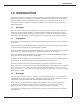
Introduction 1.0 INTRODUCTION This manual will provide connection and mounting instructions for Newall's Absolute, Digital and Distance Coded linear encoders. It is important that you read and understand this manual prior to commencing the hardware installation. Electronic specifications can be found in the corresponding integration manual. If you have any questions relating to this manual or installation contact Newall or your local authorised Newall representative. 1.
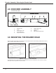
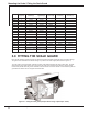
Encoder Assembly / Mounting the Reader Head 2.0 ENCODER ASSEMBLY Less than 2.5m (100”) Item 1 2 3 4 5 Description Reader Head Scale Scale Support Link Scale Anchor Pin Support Pillar Short Item 6 7 8 9 Description Support Pillar Long Scale Cover M5 Nut M8 x Socket Button Head 3.0 MOUNTING THE READER HEAD Mount the reader head together with its bracket(s) to the machine and secure the assembly parallel with axis travel to within +/-0.05mm (0.002"), (Refer to Figure 3.1). Figure 3.
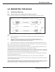
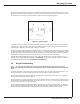
Mounting the Scale 4.0 MOUNTING THE SCALE 4.1 Double End Mounting Note: Refer to section 4.3 for mounting scales in excess of 2.5 metres. Each end of the scale is different and can be identified by the “calibration adjustment end” and the “fixed end. Figure 4.1 -Scale NOTES: (A) Erroneous readings will occur if the reader head is allowed to travel beyond the effective travel limits (Refer to Figure 4.1).
Mounting the Scale A maximum of two support pillars may be screwed together to allow for sufficient adjustment of the scale. If two pillars are insufficient to enable the scale to be mounted, then additional brackets will be necessary. These brackets must be sufficiently rigid to eliminate any axial movement of the scale. Loosely fit the support link/pin assembly onto the pillar and pass the scale through the reader head and into the support pin.
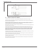
Mounting the Scale Remove the link/pin assembly and the scale from the reader head. Drill and tap M8 x 18mm deep (USA 5/16" -18 x 3/4" deep) into the machine casting as marked by the transfer punch. Fit the pillar(s) to the machine casting by using one of the methods shown in Figure 4.3. The pillar shoulder fit square and flush to the machine surface. Figure 4.3 - Support pillars A maximum of two support pillars may be screwed together to allow for sufficient adjustment of the scale.
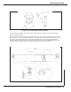
Mounting the Scale 58.00 SINGLE END MOUNTING BLOCK 10.00 25.40 30.00 FIXING SLOT FOR M6 SCREW JACKING SCREWS M5 Figure 4.4 - Single end mounting 4.3 Scales in Excess of 2.5 Meters Traverse the machine to fullest extent of travel including hand winding past any electrical limits or trip dogs. Insert the set up tube into the reader head, allowing for a sufficient amount of scale to project from the reader head in order to fit the scale mounting brackets.
Mounting the Scale Figure 4.5 - Long scale support bracket assembly For scales which are mounted in the horizontal position, spring loaded scale supports are included and should be positioned according to Table 1. Once the locations for the supports have been determined, the reader head should be positioned in the location where the first support is to be fitted. Assemble the support unit, including the jack plate if required.
Mounting the Scale / Fitting the Scale Guard FROM FIXING BRACKET Right Side (B) Left Side (A) Length No.
Cable Routing / Final Check 6.0 CABLE ROUTING The most important and the most over looked aspect of fitting the linear encoder is proper cable routing. Dangling and loose cables can be snagged or broken causing irreparable damage. Care should be taken in order to ensure that the cables are secured to the machine and that cable loops do not interfere with any part of the machine or the linear encoder movements. “P” clips and thread forming screws are provided to route the cables from the reader head.
Appendix A Appendix A - SCALE BRACKET MOUNTING OPTIONS Outboard scale support mounting Scale supports inverted 11 Newall Measurement Systems
Appendix B Appendix B - DIMENSIONAL DRAWING Newall Measurement Systems 12
Appendix B (cont’d) Appendix B - DIMENSIONAL DRAWING 13 Newall Measurement Systems
Notes Newall Measurement Systems 14
NEWALL MEASUREMENT SYSTEMS LTD HEAD OFFICE Newall Measurement Systems Ltd. Technology Gateway, Cornwall Road South Wigston Leicester LE18 4XH United Kingdom Telephone: +44 (0)116 264 2730 Facsimile: +44 (0)116 264 2731 Email: sales@newall.co.uk Web: www.newall.co.uk Newall Electronics, Inc. 1778 Dividend Drive Columbus, OH 43228 Telephone: +1 614 771 0213 Toll Free: 800.229.4376 Facsimile: +1 614 771 0219 Email: sales@newall.com Web: www.newall.com 023-80620/03-UK .