
Specifications

34
Circuit Description
Introduction
The SR530 Lock-in amplifier is an integrated
instrument combining state of the art analog design
with advanced microprocessor based control and
interfaces. This discussion is intended to aid the
advanced user in gaining a better understanding of
the instrument.
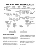
The SR530 has eight main circuit areas: the signal
amplifier, the reference oscillator, the demodulator,
the analog output and controls, the front panel, the
microprocessor, the computer interfaces, and the
power supplies. With the exception of the front
panel, the quadrature oscillator and demodulator,
and a few pieces of hardware, the entire lock-in is
built on a single printed circuit board. Each section
is isolated from the others as much as possible to
prevent spurious signal pickup. To aid in the
location of individual components, the first digit (or
first two digits of a four digit part number) of each
part number generally refers to the schematic sheet
number on which it occurs. To help find the part on
the circuit board, the parts list includes a location on
the circuit board for each component. Parts with a
four-digit part number beginning with 10,11, or 12
are found on the quadrature detector plug-in board
located in the center of the main circuit board. Part
numbers beginning with 6 refer to parts on the front
panel.
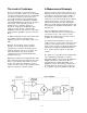
Signal Amplifier
Assuming the input selector switch is set to a voltage
input, the signal is coupled in through capacitors
C101 and C102. The input impedance is set by the
100 MΩ resistors R101 and R102 over the operating
frequency range. Note that R103 isolates the signal
shields from the instrument ground forcing the return
signal current back along the cable shields. The
signal is then applied differentially to the gates of
Q101. Q101 is a low noise dual JFET. The drain
current through R109 is kept constant by 2/2 U101.
The other half of U101 maintains a virtual null
between the drains of the two transistors and thus
an identical current flows through R110. Any input
that would cause a differential between the two
drains is amplified by 1/2 U101 and fed back via
R112 in such a way as to reduce that differential.
Since the two transistors are at equal and constant
currents, their gate-source potentials are constant.
Thus, the fed back signal which appears at the
source of the right hand transistor exactly matches
the input . Likewise, this signal will match the input
to the left hand transistor but with the opposite
sign. Resistors R112 and R110 attenuate the
fed back signal from the output of U101 resulting
in a differential input, single ended output, fixed
gain of 10 amplifier. P101 adjusts the current
balance between the two transistors and
therefore their gain match and common mode
rejection.
The output of the pre-amp is scaled by resistors
R119-R122 and analog switch U103 which
make up a 1-2-5-10 attenuator. The signal is
then amplified by 2/2 U102. Input overload is
sensed through diodes D101-D104.
Current Amplifier
When the input selector is set to current, the
input to the pre-amp comes from the output of
the current to voltage converter, 1/2 U102.
U102 is a low voltage-noise bipolar op amp.
Q102 serves as an input buffer to provide low
current-noise to the input. The op amp always
maintains a null at the gates of Q102 thus
providing an input impedance of 1KΩ (R128).
The input current is converted to a voltage by
R135 and the op amp. Q103 bootstraps out the
summing junction capacitance of Q102.
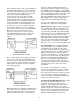
Notch Filters
U107 is a high Q, line frequency, notch filter
which can be switched in and out by analog
switch 1/4 U106. The frequency and depth of
the filter can be adjusted with P102 and P103.
Resistors R146-R149 and switch U108 make up
a selectable attenuator. U118 is a line
frequency 2nd harmonic notch filter selected by
2/4 U106. P104 and P105 adjust the frequency
and depth. The second notch filter has a gain of
3 and its output is scaled by U110 and resistors
R156-R159. The signal then takes two paths; to
inverting amplifier U111 and to the input of the
tracking bandpass filter. U111 has the same
gain as the bandpass filter. The output of either
U111 or the bandpass filter is selected by 3/4
U112 and 4/4 U106 and amplified by U113.
U114 and U115 provide a last stage of gain and
scaling and the final output is ac coupled and
buffered by 4/4 U208.
Bandpass Filter
The bandpass filter is a three op amp state-
variable active filter. 3/4 of U201 make up the
three op amps of the standard filter. U203,