Dolphin StorExpress DSE4XM1 DSE4XM2 User Guide for Windows Revision Information: Revision 0.3 Dolphin Interconnect Solutions www.dolphinics.
March 2009 Dolphin Interconnect Solutions believes the information in this publication is correct; however, the information is subject to change without notice. Dolphin Interconnect Solutions does not claim that the use of its products in the manner described in this publication will not infringe on any existing or future patent rights, nor do the descriptions contained in this publication imply the granting of licenses to make, use, or sell equipment or software in accordance with the description.
Contents 1 2 3 Introduction 1.1 System Requirements . . . . . . . . . . . . . . . . . . . . . . . . . . . . . . . . . . . . . . . . . . . . . . . . . . . . . . . . . 5 1.2 DSE4XM Components . . . . . . . . . . . . . . . . . . . . . . . . . . . . . . . . . . . . . . . . . . . . . . . . . . . . . . . . 5 1.3 Features and Performance . . . . . . . . . . . . . . . . . . . . . . . . . . . . . . . . . . . . . . . . . . . . . . . . . . . . . 6 1.4 1.4.1 1.4.2 1.4.3 1.4.4 Specifications . . . . . . . . .
3.4 3.4.1 3.4.2 Manual Installation Procedures . . . . . . . . . . . . . . . . . . . . . . . . . . . . . . . . . . . . . . . . . . . . . . . 36 Manual Install on Windows XP Pro or Windows Server 2003 . . . . . . . . . . . . . . . . . . . . . . 36 Manual Install on Windows Vista or Windows Server 2008 . . . . . . . . . . . . . . . . . . . . . . . 38 3.5 Command Line Utilities Reference . . . . . . . . . . . . . . . . . . . . . . . . . . . . . . . . . . . . . . . . . . . . . 41 3.6 Enabling SNMP. . . . .
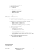
1 Introduction Congratulations on your purchase of a Dolphin StorExpress product. This guide provides user instructions for the following StorExpress models: • DSE4XM1 • DSE4XM2 These products are part of the DSE4XM family of StorExpress products. Dolphin’s StorExpress is a PCI Express based solid state storage system designed to deliver superior response times and storage capacity. Providing large capacity and fast direct storage, StorExpress connects directly to any PCI Express system.
• DXH510 PCI Express host adapter card • DXH510 half-height bracket • 2 - 1m CX4 cables • StorExpress USB Key, containing – DSE4XM User’s Guide for Windows – DSE4XM User’s Guide for Linux – ioManager User’s Guide • Quick Start Instructions • Configuration Sheet 1.
1.4 Specifications 1.4.1 Mechanical The following specifications are for the DSE4XM chassis: • Standard 4U rackmount chassis • Dimensions • – Height: 6.96” (4U /176.8mm) – Depth: 18.9 (480mm) – Width: 19” (483mm) Weight approximately 32lbs (14.5kg) 1.4.2 Environmental • Operating Temperature: 00C to 500C ambient • Storage Temperature: -200C to 700C • Relative Humidity: 15-85% non-condensing 1.4.
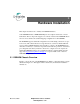
2 Hardware Installation This chapter describes how to install your DSE4XM hardware. Your DSE4XM includes a DXH510 PCI Express host adapter card and two 1-meter CX4 cables. These components support a x8 connection between the DSE4XM chassis and one server, which is the standard shipping configuration for the DSE4XM. The DSE4XM supports additional configurations accommodating connections to up to four servers, with a fixed amount of storage allocated to each server.
Figure 2–1 DSE4XM Chassis Rear Table 2–1 DSE4XM Chassis Rear Features Label Name A AC Power Inlet B AC Power Switch C Uplink Slot 0 D Uplink Slot 1 E ioDrive SSD Slot F For Manufacturing Use Only C/D - 0 Connector P0 C/D - 1 Connector P1 Figure 2–2 shows the front of the DSE4XM chassis with the front cover open. March 10, 2009 Dolphin Interconnect Solutions www.dolphinics.
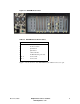
Figure 2–2 DSE4XM Chassis Front Caution: For protection of the StorExpress devices, we recommend that you do not attempt to service or remove the cover of your DSE4XM chassis. However, if you do, power should be disconnected from the chassis prior to servicing the chassis or removing the cover for any reason. In order to disconnect power remove the power cord from its receptacle in the back of the chassis as shown in Figure 2–1. The front power switch is not a disconnect switch for system power. 2.
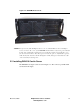
Figure 2–3 DXH510 Adapter Card Caution: Electrostatic discharge (ESD) can damage electronic components. Be sure that you are properly grounded prior to any hardware installation procedure using an ESD protection device such as a wrist strap. If you are installing the DXH510 in a low-profile system and need to use the half-height bracket, please refer to the Section 2.2.1. 1. Locate the serial number on the back of your DXH510 and record it for future reference. 2.
You have completed the hardware installation of the DXH510 into the server. If you are connecting multiple servers to the DSE4XM chassis, repeat this process for each server. Each server requires a DXH510 host adapter to connect to the DSE4XM chassis. If you are making a dual x8 connection to a single server, locate a second PCI Express slot and install the second DXH510 adapter. 2.2.
Figure 2–4 DXH510 Adapter Card Rear View 2.3 Connecting the DXH510 to Chassis A server connects to the DSE4XM chassis using the DXH510 PCI Express host adapter card. One or two cables are used to connect the DXH510 to the DSE4XM chassis. One cable provides a x4 (8 Gbps) connection; two cables provide a x8 (16 Gbps) connection. Two 1-meter cables (Model DXC1M-A) are provided as a part of the standard DSE4XM package.
One set of connectors can be used for a x8 connection when cabled to a single DXH510, or for two x4 connections when each connector in the set is cabled to a different DXH510 adapter card. Two sets of two connectors allow for connection to up to four DXH510 adapter cards in this manner. Each DXH510 card has one pair of connectors, as shown in Figure 2–1 on Page 9. Both connectors are used for a x8 connection, or a single connector may be used for a x4 connection.
Figure 2–5 DSE4XM with One x8 Connection Figure 2–6 DSE4XM with Four x4 Connections Figure 2–7 DSE4XM with Two x8 Connections March 10, 2009 Dolphin Interconnect Solutions www.dolphinics.
Note: Cables should be strain relieved or strapped to a cabinet/rack to ensure additional reliability. Note: Cables should be connected according to the configuration of your DSE4XM product. The configuration is documented on the configuration sheet included with your product. The standard StorExpress configuration is single server. Multiple server configurations require additional DXH510 adapter cards and cables, which may be purchased through http://www.dolphinics.com. 2.4 Powering up the DSE4XM 1.
6. Follow the procedure outlined in Chapter 3 for driver software installation. If you are prompted by the operating system for a driver, click Cancel. 7. Repeat the power-on procedure for any additional servers you may have connected to the DSE4XM. Note: If you are running a Windows operating system, Dolphin provides drivers to support the DXH510. These drivers are available on the Dolphin website at www.dolphinics.com/ support 2.
3 Software User Guide 3.1 Software Installation This section describes how to install software for your DSE4XM product. The DSE4XM storage device is the Fusion-IO ioDrive. The software will reference ioDrive. 3.1.1 New ioDrive Installation To install the ioDrive software on a new system: 1. Make sure you have completed the DSE4XM hardware installation steps in Chapter 2. 2. If you want to use SNMP with your ioDrive, review Section 3.6 for details on that part of the installation. 3.
When Setup creates the Fusion-io folder on the drive, it also creates these sub-folders: 7. – Docs—for the ioDrive User documentation – Driver—for the latest ioDrive Windows driver – Firmware—for the latest ioDrive firmware – ioManager—for the administrator console software and manual – SNMP—for components of SNMP – Utils—for the ioDrive command line utilities Proceed to the appropriate section to continue: – Section 3.1.
3.1.3 Outdated Firmware Check on Windows XP Pro or Windows 2003 Server After installing the ioDrive software, check the Windows System Event Log for fiodrive entries. These entries will show details of the ioDrive driver status. To view the Windows System Event Log: 1. Choose Start > Control Panel 2. Click on Administrative Tools. 3. Click on Event Viewer. 4. Click on System in the console tree. The System Event Log appears in the dialog. 5. Click on the Source column to resort the list by source. 6.
If there is a fiodrive error entry warning of old firmware, follow the instructions in the Section 3.2.4.3 later in this guide to update the firmware. If the System Event Log shows no fiodrive error entries (as in the example above), then your ioDrive is ready to receive a Windows file system. If you choose to enable SNMP support, continue to Section 3.6. 3.1.
5. Select System in the console tree. The System Event Log appears in the dialog. 6. Click the Source column to re-sort the list by source. 7. Scroll through the list to identify any fiodrive error entries. 8. Highlight an entry in the list to view its details. Check to see if there is a fiodrive Error entry that reads “ioDrive (x) firmware is too old”. (The x is the number of the ioDrive you just installed.) March 10, 2009 Dolphin Interconnect Solutions www.dolphinics.
If there is a fiodrive error entry warning of old firmware, as in the example above, follow the instructions in the Section 3.2.4.3 later in this guide to update the firmware. If the System Event Log shows no fiodrive error entries, then your ioDrive is ready to receive a Windows file system. If you choose to enable SNMP support, refer to Section 3.6. 3.1.5 ioDrive Naming The ioDrive receives a name and number as part of the install process for identification.
Note: The system manufacturer assigns bus numbers, which can range from 0 on up. These numbers may or may not reflect the physical location of the bus. For example, the second slot from the edge of the motherboard may be Bus 2, but it could also be Bus 16 or another arbitrary number. Checking Device Manager is one way to confirm the specific bus number for your installation. You can also use ioManager to view this number.) 3.1.
5. Locate and right-click the ioDrive in the list of storage devices on the right. (If the ioDrive does not appear in the list, choose Rescan Disks from the Action menu. You may also need to restart your computer to display the ioDrive in the list.) 6. Click Initialize Disk. You can now use the Disk Management Utility to add a file system to your ioDrive. 3.1.7 Creating a RAID Configuration You can use your ioDrive as part of a RAID configuration. To do so, you must format your ioDrive as a dynamic volume.
Table 3–1 ioDrive Slot LED Indicators Green Yellow OFF OFF Amber/ Red* OFF ON OFF ON ON OFF OFF ON FLASH OFF FLASH OFF OFF Power on (driver not loaded) Power on (driver loaded) Writing (rate indicates volume of writes) Reading (rate indicates volume of reads) ON ON ON Location beacon Indicates Notes Power off Load driver Can appear in combination with the Read LED Can appear in combination with the Write LED Also appears during a firmware update * Later versions of the ioDrive use
3.2.4 Common Maintenance Tasks The most common tasks involve drivers and firmware. 3.2.4.1 Uninstalling the ioDrive Windows Driver To uninstall the ioDrive Windows driver: 1. Go to Start > Control Panel. 2. Click Administrative Tools. 3. Click Computer Management. 4. Click Device Manager in the console tree at the left. 5. Expand the Fusion-io Devices item. (Select System Devices for pre-1.2.3 drivers.) 6. Right-click on the desired ioDrive. 7. Click Uninstall. Windows will uninstall the driver. 3.2.4.
3.2.4.3 Upgrading the ioDrive Firmware Caution: You should upgrade the firmware only if the System Event Log reports out-of- date firmware or if instructed to do so by Dolphin Customer Support. 3.2.4.3.1 Viewing the Firmware Version You can view the ioDrive’s firmware version using the Windows System Event Log. You can then use this information to evaluate upgrading to a newer firmware release. To view the firmware version in the System Event Log: 1. Choose Start > Administrative Tools. 2.
3.2.4.3.2 Performing the Upgrade Warning: It is extremely important that the power not be turned off to either the server or the DSE4XM chassis during a firmware upgrade, nor should the cable be disconnected. Power or connectivity loss during a firmware upgrade could cause device failure. Consider adding a UPS to the system prior to performing a firmware upgrade to prevent this from happening. Caution: You should back up the data on the ioDrive prior to any upgrade as a precaution.
will completely power up the DSE4XM chassis, to complete the firmware upgrade. (It must be a power down and restart of both the server and the chassis to ensure a complete reset of the+ system and the ioDrive(s). If there are multiple servers connected to the DSE4XM chassis, these servers should be powered down as well, and powered back up after the DSE4XM is powered up.) 3.2.
This will create a new DWORD parameter registry key called AutoAttach with a hex value in: HKEY_LOCAL_MACHINE\SYSTEM\CurrentControlSet\Services\fiodrive\Parameters Your ioDrive will now not automatically attach the next time you reboot the computer. When you finish troubleshooting the driver issue, use ioManager to attach the ioDrive(s) and make them available to Windows. 3.2.6.1 Enabling Auto-Attach To re-enable auto-attach after disabling it with the autoattachenable.reg file: 1. Choose Start/Run. 2.
3.3 Troubleshooting Event Log Messages The Windows System Event Log will display fiodrive messages concerning the ioDrive—both Informational and Warnings. Note: Each ioDrive is numbered from 0 upwards. These numbers reflect the PCIe bus number where you installed the device. Use ioManager to view this number for your device. The following are the most common Event Log error messages. Message: Error: ioDrive(x) firmware is too old. The firmware must be updated.
Message: Error: The ioDrive(x) initialization failed with error code 0xerrorcode (where errorcode is a number which may vary) Suggested Solutions: • Reinstall the Windows driver • Remove and reseat the ioDrive device • Remove and insert the ioDrive in a different PCIe slot If these do not correct the error, please contact Dolphin Customer Support. Message: Error: The ioDrive(x) was not attached. Use the fio-attach utility to rebuild the drive. March 10, 2009 Dolphin Interconnect Solutions www.
Suggested Solution: This error may appear if the system shut down abruptly or hung. You can use either the fio-attach command line utility or ioManager to re-attach the ioDrive. This attach process may take up to ten minutes as the utility rebuilds the drive. Message: Warning: The ioDrive(x) was not attached because auto-attach is disabled. March 10, 2009 Dolphin Interconnect Solutions www.dolphinics.
Suggested Solution: The ioDrive must attach to the Windows operating system to be available to users and applications. (This attach normally occurs at boot time.) As part of this attach process, the ioDrive driver checks to see if there is an AutoAttach parameter in the Windows registry. If you create this Registry parameter to disable auto-attach, the attach operation does not complete. The driver will then display this message. To attach an unattached ioDrive: 1. Run ioManager. 2.
To re-enable Auto Attach at boot time, refer to the section on Enabling Auto Attach. 3.4 Manual Installation Procedures The Windows Setup program should install your needed driver and software. However, if the driver does not install, you can perform a manual install (or upgrade) using the steps below for either Windows XP Pro/Server 2003 or Windows Vista/Server 2008. 3.4.
5. Click Browse next to the path field. Windows will display a file dialog. 6. Select the folder with the ioDrive driver (the default is Program Files\Fusionio\driver). 7. Click OK. Windows will find the correct driver and install the device software. When the driver install completes, Windows will display this message: March 10, 2009 Dolphin Interconnect Solutions www.dolphinics.
Proceed to the appropriate Windows section in this guide to perform an outdated firmware check. 3.4.2 Manual Install on Windows Vista or Windows Server 2008 The Windows Driver Wizard will automatically detect the new ioDrive and start to locate its driver after you restart the system. To complete the install: 1. Windows will ask you to locate the software driver. March 10, 2009 Dolphin Interconnect Solutions www.dolphinics.
2. Click Browse my computer for driver software. The Setup program will ask you for a path to search. March 10, 2009 Dolphin Interconnect Solutions www.dolphinics.
3. Click Browse next to the path field. Windows will display a file dialog. 4. Select the folder with the ioDrive driver (the default is Program Files\Fusionio\driver). 5. Click OK. 6. Click Next. Windows will find the correct driver and install the device software. When the driver install completes, Windows will display this message: March 10, 2009 Dolphin Interconnect Solutions www.dolphinics.
Proceed to the appropriate section for your Windows version to perform the outdated firmware check. 3.5 Command Line Utilities Reference The Windows Setup package installs various utilities into the Program Files\Fusionio\utils folder. These provide a number of useful ways to access, test, and manipulate the ioDrive via the command line (Command Prompt).
fio-attach Description Attaches the ioDrive and makes it available to Windows. You can then partition, format, or set up the ioDrive as part of a RAID array using the Windows Disk Management utility. This command displays a progress bar and percentage as it completes the attach process. Note: In most cases, the ioDrive driver automatically attaches the device at boot time.
where is the name given by the ioDrive driver to your device. This name is /dev/fctx where x indicates the device number. (The number reflects the PCIe bus for the ioDrive.) For example, the name /dev/fct4 refers to the ioDrive installed in PCIe Bus 4 in your Windows system. (Use ioManager or fio-status to view this number.) Options -i Immediate: Causes a forced immediate detach (does not save metadata) -q Quiet: Runs the Detach process without displaying the progress bar or percentage.
Options -q -s -f -u Quit on erase error. Sets the storage size by a number and one of the following units as a suffix: • % Percentage of drive for user data • t/T Number of terabytes to format • g/G Number of gigabytes to format • m/M Number of megabytes to format For example, setting the size as either 90% or 72GB on an 80GB ioDrive both result in the same capacity for user data—72GB. Force size: Bypass sizing sanity checks to enable 64bit address space.
-c -a Count: Report only the number of ioDrives installed. All: Print all available information for each device. The fio-status command displays the following information: • Serial number • Hardware UID • Part number • Bus ID • Manufacturer's name • Vendor ID • Manufacturing date • Subsystem vendor and device IDs • Firmware version at manufacturing time • Device ID • Size of the device, out of total capacity • PCI slot number • NAND manufacturer • Internal temperature (avg. and max.
ioDimm3 SN:0719 PN:001195011, Mfr:000 Date:20080709 Firmware v11791 92 GBytes, 8192 blocks, 256 pages, 47264 bytes/page (25 pads, 1 plane, 4 banks) Nand: Samsung (ec) SLC Error correction: 11 bits per 240 bytes, retire above 4 bits FPGA ID:000 UID:0000000002cf01326845000048f00c00 PCI: 02:00.0, Slot Number:2 Vendor ID: 1aed Device ID: 1003 Ambient temperature: 40 degC Internal temperature: avg 44.3 degC, max 50.7 degC Media status: healthy. 99.78% blocks good. data:99.
Options -d Updates the specified device. Use /dev/fctx where x is the device’s PCIe bus number. (Use fio-status to view this.) -f Force Upgrade (Also used to perform a rollback to an earlier firmware version.) -l List firmware available in the archive. Pretend: Show what updates would be done (the firmware is not modified). This option requires the -d option. Runs the update process without displaying the progress bar or percent completed.
SOFTWARE\Fusion-io\io-snmp-win\CurrentVersion 6. Save and exit Regedit. 7. Stop and restart the Windows SNMP service. You can now monitor your ioDrive using SNMP. By default, the ioDrive agent uses the cpqIODrv.mib in the Program Files\Fusion-io\SNMP folder. (Refer to the Release Notes for further details on the MIB.) 3.6.1 Windows Management Instrumentation (WMI) WMI is the Microsoft implementation of the Common Information Model (CIM) and Web-Base Enterprise Management (WBEM).
C:\WINDOWS\system32\wbem\snmp\smi2smir /g RFC1213-MIB.txt cpqHost.mib cpqIODrv.mib > cpqIODrv.mof 4. To register this MOF file with WMI, type in the command: C:\WINDOWS\system32\wbem\mofcomp cpqIODrv.mof Your management system is now ready for active monitoring. March 10, 2009 Dolphin Interconnect Solutions www.dolphinics.