User Manual
Manuals
Brands
Microsoft Manuals
webcams
UNO-3074
71
72
73
74
75
76
77
78
79
80
65
Appendix A
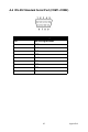
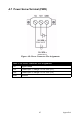
A.7 Power Scre
w T
e
rminal (PWR)
Figure A.8: Power
Connector Pin
Assignment
s
T
able A.10: Power Connector Pin Assignment
s
Pin
Signal Name
+Vs
Po
wer input 1; Range: 16~36 VDC (P1)
+Vs*
Po
wer input 2; Range: 16~36 VDC (P2)
GND
Ground
1
...
...
73
74
75
76
77
...
...
80